
Arduino-Based Line Following Robot with L298N Motor Driver and IR Sensor Array
View and Edit Project In Cirkit Designer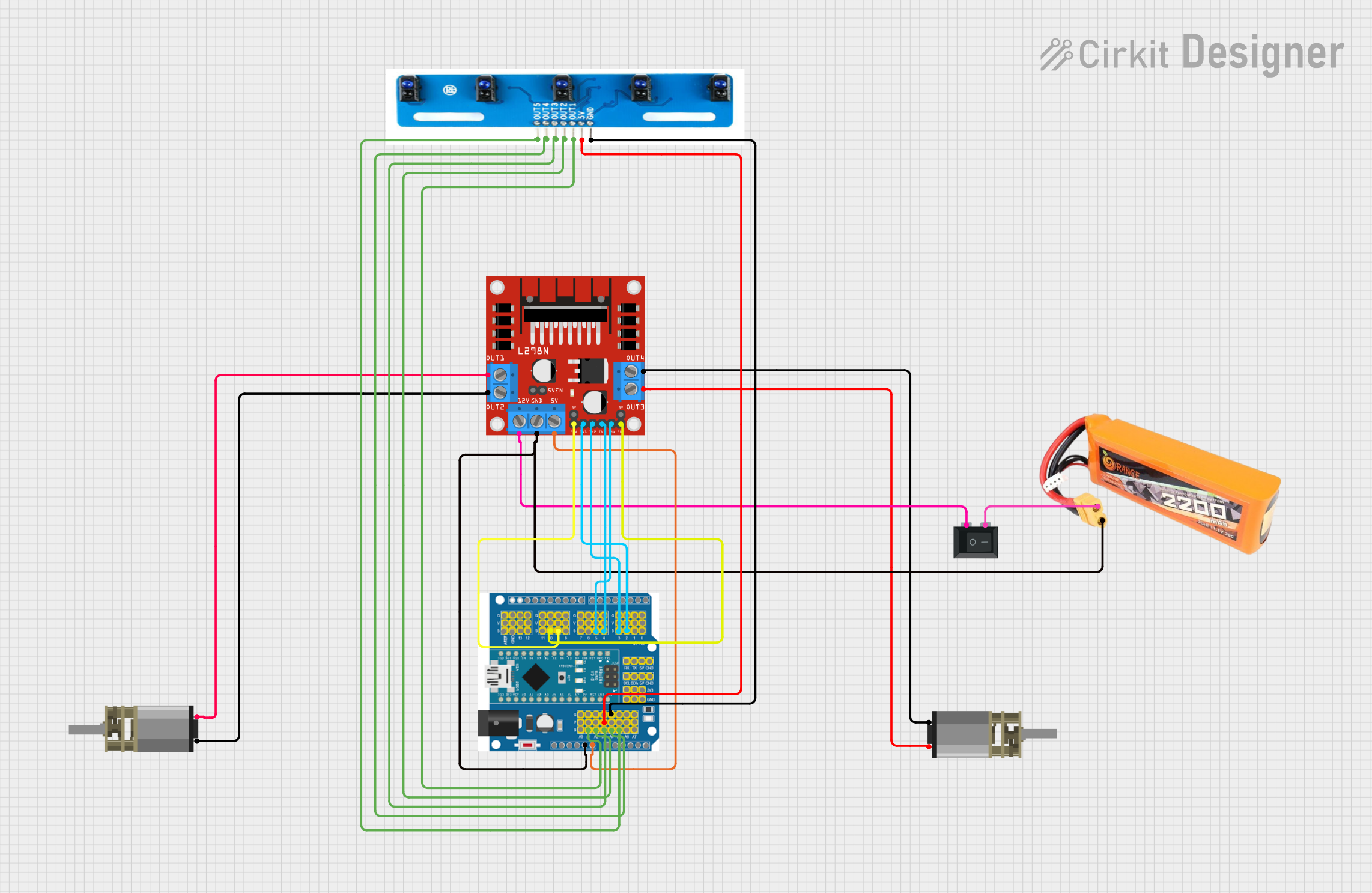
Circuit Documentation
Summary
This document provides a detailed overview of a circuit designed to control two DC motors using an Arduino Expansion Board, an L298N motor driver, and a 5-channel IR sensor array. The circuit is powered by a LiPo battery and includes a rocker switch for power control. The Arduino is programmed to read the IR sensor values and adjust the motor speeds accordingly to follow a line.
Component List
L298N DC Motor Driver
- Description: Dual H-Bridge motor driver for controlling two DC motors.
- Pins: OUT1, OUT2, 12V, GND, 5V, OUT3, OUT4, 5V-ENA-JMP-I, 5V-ENA-JMP-O, +5V-J1, +5V-J2, ENA, IN1, IN2, IN3, IN4, ENB
DC Mini Metal Gear Motor
- Description: Small DC motor with metal gears for increased torque.
- Pins: IN1, IN2
DC Mini Metal Gear Motor
- Description: Small DC motor with metal gears for increased torque.
- Pins: IN1, IN2
LiPo Battery 2200mAH 30C
- Description: Rechargeable lithium polymer battery.
- Pins: VCC, GND
Arduino Expansion Board
- Description: Expansion board for Arduino with multiple I/O pins.
- Pins: 8, 9, 10, 11, 12, 13, GND, AREF, RX, TX, 2, 3, 4, 5, 6, 7, G, V, 1, 0, 5V, SCL, SDA, 3V3, A0, A1, A2, A3, A4, A5, A6, A7, RST, NC, VIN, POWER
5 Channel IR Array
- Description: Infrared sensor array for line following applications.
- Pins: Ground, VCC (5V), OUT-1, OUT-2, OUT-3, OUT-4, OUT-5
Rocker Switch (SPST)
- Description: Single-pole single-throw switch for power control.
- Pins: 1, 2
Wiring Details
L298N DC Motor Driver
- ENB connected to Pin 10 on Arduino Expansion Board
- ENA connected to Pin 9 on Arduino Expansion Board
- IN4 connected to Pin 5 on Arduino Expansion Board
- IN3 connected to Pin 4 on Arduino Expansion Board
- IN2 connected to Pin 3 on Arduino Expansion Board
- IN1 connected to Pin 2 on Arduino Expansion Board
- GND connected to GND on Arduino Expansion Board and GND on LiPo Battery
- 5V connected to VIN on Arduino Expansion Board
- OUT1 connected to IN2 on DC Mini Metal Gear Motor
- OUT2 connected to IN1 on DC Mini Metal Gear Motor
- OUT3 connected to IN2 on DC Mini Metal Gear Motor
- OUT4 connected to IN1 on DC Mini Metal Gear Motor
- 12V connected to Pin 1 on Rocker Switch
DC Mini Metal Gear Motor
- IN2 connected to OUT1 on L298N DC Motor Driver
- IN1 connected to OUT2 on L298N DC Motor Driver
DC Mini Metal Gear Motor
- IN2 connected to OUT3 on L298N DC Motor Driver
- IN1 connected to OUT4 on L298N DC Motor Driver
LiPo Battery 2200mAH 30C
- GND connected to GND on Arduino Expansion Board and GND on L298N DC Motor Driver
- VCC connected to Pin 2 on Rocker Switch
Arduino Expansion Board
- Pin 10 connected to ENB on L298N DC Motor Driver
- Pin 9 connected to ENA on L298N DC Motor Driver
- Pin 5 connected to IN4 on L298N DC Motor Driver
- Pin 4 connected to IN3 on L298N DC Motor Driver
- Pin 3 connected to IN2 on L298N DC Motor Driver
- Pin 2 connected to IN1 on L298N DC Motor Driver
- G connected to Ground on 5 Channel IR Array
- V connected to VCC (5V) on 5 Channel IR Array
- A1 connected to OUT-1 on 5 Channel IR Array
- A2 connected to OUT-2 on 5 Channel IR Array
- A3 connected to OUT-3 on 5 Channel IR Array
- A4 connected to OUT-4 on 5 Channel IR Array
- A5 connected to OUT-5 on 5 Channel IR Array
- GND connected to GND on LiPo Battery and GND on L298N DC Motor Driver
- VIN connected to 5V on L298N DC Motor Driver
5 Channel IR Array
- Ground connected to G on Arduino Expansion Board
- VCC (5V) connected to V on Arduino Expansion Board
- OUT-1 connected to A1 on Arduino Expansion Board
- OUT-2 connected to A2 on Arduino Expansion Board
- OUT-3 connected to A3 on Arduino Expansion Board
- OUT-4 connected to A4 on Arduino Expansion Board
- OUT-5 connected to A5 on Arduino Expansion Board
Rocker Switch (SPST)
- Pin 1 connected to 12V on L298N DC Motor Driver
- Pin 2 connected to VCC on LiPo Battery
Code Documentation
// Pin definitions
const int motor1Pin1 = 2; // IN1 on L298N
const int motor1Pin2 = 3; // IN2 on L298N
const int motor2Pin1 = 4; // IN3 on L298N
const int motor2Pin2 = 5; // IN4 on L298N
const int enableA = 9;    // ENA on L298N
const int enableB = 10;   // ENB on L298N

const int irSensor1 = A1; // OUT-1 on IR array
const int irSensor2 = A2; // OUT-2 on IR array
const int irSensor3 = A3; // OUT-3 on IR array
const int irSensor4 = A4; // OUT-4 on IR array
const int irSensor5 = A5; // OUT-5 on IR array

// PID constants
float Kp = 0.5;
float Ki = 0.0;
float Kd = 0.1;

float lastError = 0;
float integral = 0;

void setup() {
  // Set motor control pins as outputs
  pinMode(motor1Pin1, OUTPUT);
  pinMode(motor1Pin2, OUTPUT);
  pinMode(motor2Pin1, OUTPUT);
  pinMode(motor2Pin2, OUTPUT);
  pinMode(enableA, OUTPUT);
  pinMode(enableB, OUTPUT);

  // Set initial motor speed
  analogWrite(enableA, 200); // Adjust speed as needed
  analogWrite(enableB, 200); // Adjust speed as needed

  // Set IR sensor pins as inputs
  pinMode(irSensor1, INPUT);
  pinMode(irSensor2, INPUT);
  pinMode(irSensor3, INPUT);
  pinMode(irSensor4, INPUT);
  pinMode(irSensor5, INPUT);

  Serial.begin(9600); // Initialize serial communication for debugging
}

void loop() {
  // Read IR sensor values
  int sensor1 = analogRead(irSensor1);
  int sensor2 = analogRead(irSensor2);
  int sensor3 = analogRead(irSensor3);
  int sensor4 = analogRead(irSensor4);
  int sensor5 = analogRead(irSensor5);

  // Debugging: print sensor values
  Serial.print(sensor1);
  Serial.print(" ");
  Serial.print(sensor2);
  Serial.print(" ");
  Serial.print(sensor3);
  Serial.print(" ");
  Serial.print(sensor4);
  Serial.print(" ");
  Serial.print(sensor5);
  Serial.println();

  // Calculate error
  float error = (sensor1 * -2 + sensor2 * -1 + sensor4 * 1 + sensor5 * 2) / (sensor1 + sensor2 + sensor3 + sensor4 + sensor5);

  // PID calculations
  integral += error;
  float derivative = error -