ESP8266-Based Soil Moisture Monitoring System with OLED Display and DHT11 Temperature Sensing
Circuit Documentation
Summary
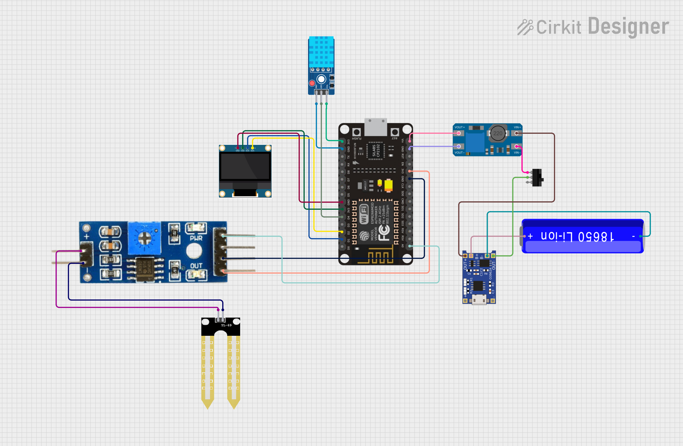
This circuit is designed to monitor soil moisture levels using an ESP-8266 microcontroller, which reads data from a soil moisture sensor and displays the information on an OLED display. The system also includes a DHT11 sensor for measuring temperature and humidity, a TP4056 module for charging a Li-ion battery, and an MT3608 boost converter to step up the voltage when necessary. A toggle switch is used to control the power supply to the circuit.
Component List
ESP-8266 Controller
- Microcontroller with WiFi capability.
- Used for reading sensor data and controlling the OLED display.
YL-69 Sonda
- Soil moisture probe.
- Measures the moisture level in the soil.
Soil Moisture Module
- Interface module for the YL-69 Sonda probe.
- Provides analog and digital outputs corresponding to the soil moisture level.
0.96" OLED
- Small display screen.
- Shows the sensor data and other information.
DHT11 Sensor V2
- Temperature and humidity sensor.
- Provides environmental data to the microcontroller.
TP4056
- Lithium-ion battery charging module.
- Charges the battery and provides power to the circuit.
MT3608
- Boost converter module.
- Steps up the voltage to the required level for the ESP-8266.
18650 Li-ion Battery
- Rechargeable battery.
- Powers the circuit.
Toggle Switch
- Mechanical switch.
- Controls the power supply to the circuit.
Wiring Details
ESP-8266 Controller
A0connected to Soil Moisture ModuleAnalogD1connected to OLEDSCKD2connected to OLEDSDAD4connected to DHT11 Sensor V2DAT3V3connected to OLEDVDD, Soil Moisture ModuleVCC, and DHT11 Sensor V2VCCGNDconnected to OLEDGND, Soil Moisture ModuleGround, DHT11 Sensor V2GND, and MT3608VOUT-Vinconnected to MT3608VOUT+
YL-69 Sonda
+connected to Soil Moisture Modulepositive-connected to Soil Moisture Modulenegative
Soil Moisture Module
VCCandGroundconnected as described above.Analogconnected to ESP-8266A0
0.96" OLED
SCKconnected to ESP-8266D1SDAconnected to ESP-8266D2VDDconnected to ESP-82663V3GNDconnected to ESP-8266GND
DHT11 Sensor V2
DATconnected to ESP-8266D4VCCconnected to ESP-82663V3GNDconnected to ESP-8266GND
TP4056
OUT-connected to Toggle SwitchCOMB-connected to 18650 Li-ion Battery-B+connected to 18650 Li-ion Battery+OUT+connected to MT3608VIN+
MT3608
VOUT+connected to ESP-8266VinVOUT-connected to ESP-8266GNDVIN+connected to TP4056OUT+VIN-connected to Toggle SwitchL1
18650 Li-ion Battery
+connected to TP4056B+-connected to TP4056B-
Toggle Switch
L1connected to MT3608VIN-COMconnected to TP4056OUT-
Documented Code
No code was provided for the microcontroller. The expected code should handle reading data from the soil moisture sensor and the DHT11 sensor, processing the data, and displaying it on the OLED screen. It should also manage WiFi connectivity if remote monitoring or control is required.
Please note that the above documentation is based on the provided parts list and electrical net list. The actual functionality and interconnections should be verified with the actual circuit design and requirements.