Cirkit Designer
Your all-in-one circuit design IDE
Home /
Project Documentation
ESP32-Controlled Dual DC Motor Driver System
Circuit Documentation
Summary
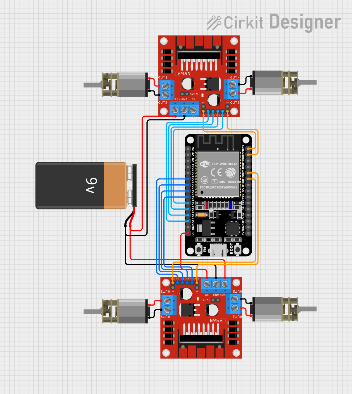
This circuit is designed to control multiple DC Mini Metal Gear Motors using two L298N DC motor drivers, which are interfaced with an ESP32 microcontroller. The ESP32 provides control signals to the motor drivers, which in turn drive the motors. A 9V battery is used to supply power to the motor drivers and the ESP32. The circuit is likely intended for applications requiring precise motor control, such as robotics or automation systems.
Component List
DC Mini Metal Gear Motor
- Description: A compact and powerful motor suitable for a wide range of applications.
- Pins: IN1, IN2
L298N DC Motor Driver
- Description: A dual H-bridge motor driver capable of driving two motors independently.
- Pins: OUT1, OUT2, 12V, GND, 5V, OUT3, OUT4, 5V-ENA-JMP-I, 5V-ENA-JMP-O, +5V-J1, +5V-J2, ENA, IN1, IN2, IN3, IN4, ENB
9V Battery
- Description: A standard 9V battery used to provide power to the circuit.
- Pins: -, +
ESP32 (30 pin)
- Description: A powerful microcontroller with Wi-Fi and Bluetooth capabilities, suitable for a variety of IoT applications.
- Pins: EN, VP, VN, D34, D35, D32, D33, D25, D26, D27, D14, D12, D13, GND, Vin, D23, D22, TX0, RX0, D21, D19, D18, D5, TX2, RX2, D4, D2, D15, 3V3
Wiring Details
DC Mini Metal Gear Motor
- Motor 1:
- IN1 connected to L298N OUT4
- IN2 connected to L298N OUT3
- Motor 2:
- IN1 connected to L298N OUT4
- IN2 connected to L298N OUT3
- Motor 3:
- IN1 connected to L298N OUT2
- IN2 connected to L298N OUT1
- Motor 4:
- IN1 connected to L298N OUT2
- IN2 connected to L298N OUT1
L298N DC Motor Driver
- Driver 1:
- IN1 connected to ESP32 D26
- IN2 connected to ESP32 D25
- IN3 connected to ESP32 D33
- IN4 connected to ESP32 D32
- ENA connected to ESP32 D21
- ENB connected to ESP32 D19
- 12V connected to 9V Battery +
- GND connected to 9V Battery -
- Driver 2:
- IN1 connected to ESP32 D13
- IN2 connected to ESP32 D12
- IN3 connected to ESP32 D14
- IN4 connected to ESP32 D27
- ENA connected to ESP32 D23
- ENB connected to ESP32 D22
- 12V connected to 9V Battery +
- GND connected to 9V Battery -
9V Battery
- connected to both L298N 12V pins
- connected to both L298N GND pins
ESP32 (30 pin)
- D32, D33, D25, D26, D27, D14, D12, D13 used for motor control signals
- D21, D19, D23, D22 used for enabling motor drivers
- Vin connected to L298N 5V (power supply for the ESP32)
Documented Code
No code was provided for the ESP32 microcontroller. The code would typically include the initialization of the GPIO pins used for motor control and the logic to drive the motors via the L298N motor drivers. It would also handle any communication or sensor integration required for the application.