
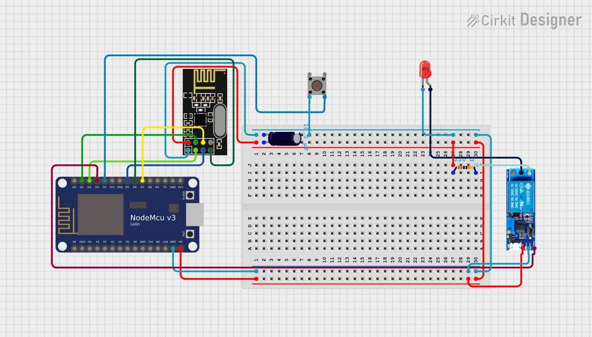
Circuit Documentation
Summary
This circuit integrates a NodeMCU V3 ESP8266 microcontroller with an NRF24L01 wireless transceiver module, a relay module, an LED, a resistor, a pushbutton, and an electrolytic capacitor. The NodeMCU is programmed to control the relay and communicate with the NRF24L01 module. The relay can be triggered by a signal from the NRF24L01 or by pressing the pushbutton. The LED indicates the relay's status, and the capacitor provides power supply filtering.
Component List
NodeMCU V3 ESP8266
- Microcontroller with WiFi capability.
- Pins: A0, GND, VU, S3, S2, S1, SC, S0, SK, 3V3, EN, RST, Vin, D0, D1, D2, D3, D4, D5, D6, D7, D8, RX, TX.
NRF24L01
- 2.4GHz Wireless Transceiver Module.
- Pins: IRQ (not used), MOSI, CSN, VCC (3V), GND, CE, SCK, MISO.
Relay Module 5v-30v
- Module for controlling high power devices.
- Pins: Common contact, Normally open, Normally closed, Trigger, V-, V+.
LED: Two Pin (red)
- Red light-emitting diode.
- Pins: Cathode, Anode.
Resistor
- 220 Ohms resistor for current limiting.
- Pins: Pin1, Pin2.
Pushbutton
- A simple push-to-make button.
- Pins: Pin 3 (out), Pin 4 (out), Pin 1 (in), Pin 2 (in).
Electrolytic Capacitor
- Capacitor with 0.00001 Farads capacitance for power supply filtering.
- Pins: -, +.
Wiring Details
NodeMCU V3 ESP8266
- Vin connected to Relay Module V+, Electrolytic Capacitor +, NRF24L01 VCC (3V), and Resistor pin1.
- GND connected to Relay Module V-, Electrolytic Capacitor -, NRF24L01 GND, Pushbutton Pin 3 (out), and LED cathode.
- D1 connected to NRF24L01 CSN.
- D2 connected to NRF24L01 CE.
- D3 connected to Relay Module trigger.
- D4 connected to Pushbutton Pin 1 (in).
- D5 connected to NRF24L01 SCK.
- D6 connected to NRF24L01 MISO.
- D7 connected to NRF24L01 MOSI.
NRF24L01
- VCC (3V) connected to NodeMCU Vin.
- GND connected to NodeMCU GND.
- CSN connected to NodeMCU D1.
- CE connected to NodeMCU D2.
- SCK connected to NodeMCU D5.
- MISO connected to NodeMCU D6.
- MOSI connected to NodeMCU D7.
Relay Module 5v-30v
- V+ connected to NodeMCU Vin.
- V- connected to NodeMCU GND.
- Trigger connected to NodeMCU D3.
- Normally open connected to Resistor pin2.
- Common contact connected to LED anode.
LED: Two Pin (red)
- Cathode connected to NodeMCU GND.
- Anode connected to Relay Module common contact.
Resistor
- Pin1 connected to NodeMCU Vin.
- Pin2 connected to Relay Module normally open.
Pushbutton
- Pin 1 (in) connected to NodeMCU D4.
- Pin 3 (out) connected to NodeMCU GND.
Electrolytic Capacitor
-
- connected to NodeMCU Vin.
-
- connected to NodeMCU GND.
Documented Code
#include <ESP8266WiFi.h>
#include <SPI.h>
#include <RF24.h>

// NRF24L01+ Pins
#define CE_PIN D2
#define CSN_PIN D1

// Relay and Push Button
#define RELAY_PIN D3
#define BUTTON_PIN D4

RF24 radio(CE_PIN, CSN_PIN); // Create NRF24L01 object

void setup() {
  Serial.begin(115200);

  // Initialize Relay and Button Pins
  pinMode(RELAY_PIN, OUTPUT);
  digitalWrite(RELAY_PIN, LOW); // Ensure relay is off
  pinMode(BUTTON_PIN, INPUT_PULLUP); // Using internal pull-up resistor

  // Initialize NRF24L01
  radio.begin();
  radio.setPALevel(RF24_PA_HIGH);
  radio.openReadingPipe(1, "00001"); // Set address for reading
  radio.startListening();

  Serial.println("Setup Complete");
}

void loop() {
  // Check for incoming RF data
  if (radio.available()) {
    char receivedText[32] = "";
    radio.read(&receivedText, sizeof(receivedText));
    Serial.println(receivedText);

    // Example action: Toggle Relay on receiving specific command
    if (strcmp(receivedText, "ACTIVATE") == 0) {
      digitalWrite(RELAY_PIN, HIGH); // Turn on relay
      delay(2000); // Keep relay on for 2 seconds
      digitalWrite(RELAY_PIN, LOW); // Turn off relay
    }
  }

  // Check if button is pressed
  if (digitalRead(BUTTON_PIN) == LOW) {
    Serial.println("Button Pressed, Activating Relay");
    digitalWrite(RELAY_PIN, HIGH); // Turn on relay
    delay(2000); // Keep relay on for 2 seconds
    digitalWrite(RELAY_PIN, LOW); // Turn off relay
  }

  delay(100); // Small delay to avoid bouncing
}
This code is designed to run on the NodeMCU V3 ESP8266 microcontroller. It initializes the NRF24L01 module and sets up the relay and pushbutton for input and output, respectively. The microcontroller listens for incoming data from the NRF24L01 module and toggles the relay when the "ACTIVATE" command is received. Additionally, the relay can be activated by pressing the pushbutton. The relay remains active for 2 seconds before turning off.