
ESP32-Based Environmental Monitoring System with NeoPixel Feedback and I2C Sensor Integration
View and Edit Project In Cirkit Designer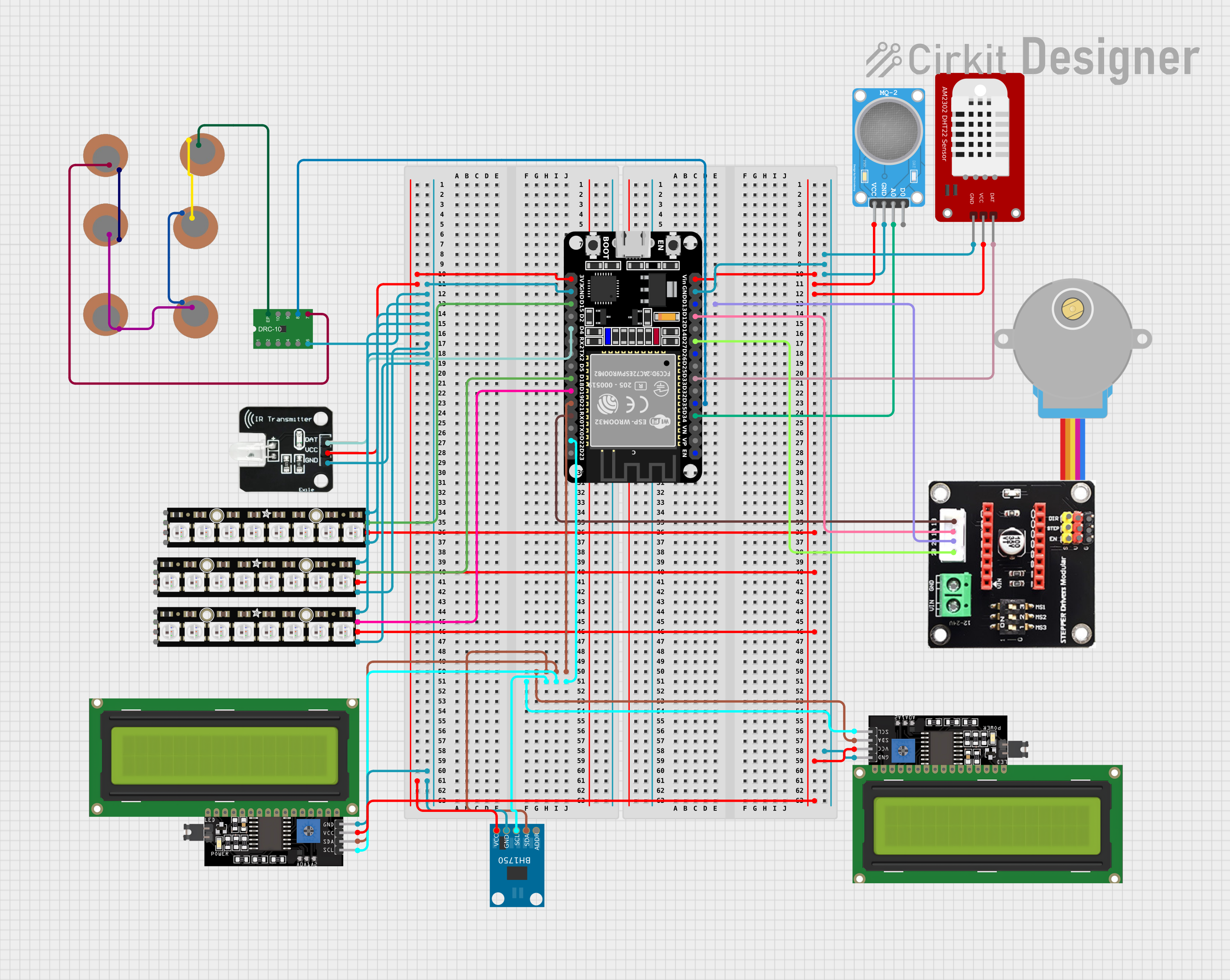
Circuit Documentation
Summary
This circuit integrates a variety of components including sensors, displays, a microcontroller, and actuators. The central processing unit of the circuit is an ESP32 microcontroller, which interfaces with environmental sensors (MQ-2, BH1750, DHT22), a gas sensor (MQ-2), a light sensor (BH1750), a temperature and humidity sensor (DHT22), and an IR transmitter. It also controls a stepper motor through a driver module and displays data on I2C LCD displays. Additionally, the circuit includes NeoPixel LED sticks for visual output and piezo sensors for detecting vibrations or impacts.
Component List
- ESP32 (30 pin): A microcontroller with Wi-Fi and Bluetooth capabilities, featuring a variety of digital and analog I/O pins.
- MQ-2 Sensor: A gas sensor used for detecting LPG, i-butane, propane, methane, alcohol, hydrogen, and smoke.
- Adafruit NeoPixel Stick: An 8-LED strip of individually addressable RGB LEDs.
- BH1750: A digital ambient light sensor that provides lux values via I2C.
- LCD Display 16x4 I2C: A 16x4 character LCD display with an I2C interface for displaying text and numbers.
- Adafruit Gear-Reduced Stepper Motor (small): A small stepper motor suitable for precise positioning applications.
- STEPPER Drivers Modular: A stepper motor driver module that controls the stepper motor.
- Piezo Sensor: A sensor that generates a voltage when it is deformed by pressure, vibration, or impact.
- DHT22: A sensor for measuring temperature and humidity.
- IR Transmitter: An infrared LED used for sending signals to IR receivers.
- Unproven: A component with various functionalities, possibly a power management or sensor interface module.
Wiring Details
ESP32 (30 pin)
- D13: Connected to the "2A" pin of the STEPPER Drivers Modular.
- D35: Connected to the "~PG" pin of the Unproven component.
- D21 (SDA): Shared I2C data line connected to BH1750, LCD Display 16x4 I2C (x2).
- D22 (SCL): Shared I2C clock line connected to BH1750, LCD Display 16x4 I2C (x2).
- GND: Common ground connected to DHT22, MQ-2 SENSOR, LCD Display 16x4 I2C, and others.
- Vin: Power input connected to MQ-2 SENSOR, DHT22, Adafruit NeoPixel Stick (x3), LCD Display 16x4 I2C (x2).
- 3V3: 3.3V power output connected to IR Transmitter, BH1750.
- D34: Connected to the "A0" pin of the MQ-2 SENSOR.
- D33: Connected to the "DAT" pin of the DHT22.
- D27: Connected to the "2B" pin of the STEPPER Drivers Modular.
- D12: Connected to the "1A" pin of the STEPPER Drivers Modular.
- RX0: Connected to the "1B" pin of the STEPPER Drivers Modular.
- D19: Connected to the "DATAOUT" pin of the Adafruit NeoPixel Stick.
- D18: Connected to the "DATAOUT" pin of another Adafruit NeoPixel Stick.
- D4: Connected to the "DAT" pin of the IR Transmitter.
- D15: Connected to the "DATAOUT" pin of another Adafruit NeoPixel Stick.
MQ-2 SENSOR
- VCC: Power input from ESP32 Vin.
- GND: Ground connection shared with ESP32.
- A0: Analog output connected to ESP32 D34.
Adafruit NeoPixel Stick
- GND: Ground connection shared with ESP32.
- DATAOUT: Data output connected to ESP32 D19, D18, or D15 depending on the instance.
- +5V: Power input from ESP32 Vin.
BH1750
- VCC: 3.3V power input from ESP32 3V3.
- GND: Ground connection shared with ESP32.
- SCL: I2C clock line shared with ESP32 D22.
- SDA: I2C data line shared with ESP32 D21.
LCD Display 16x4 I2C
- SCL: I2C clock line shared with ESP32 D22.
- SDA: I2C data line shared with ESP32 D21.
- VCC: Power input from ESP32 Vin.
- GND: Ground connection shared with ESP32.
STEPPER Drivers Modular
- 2B: Connected to ESP32 D27.
- 2A: Connected to ESP32 D13.
- 1A: Connected to ESP32 D12.
- 1B: Connected to ESP32 RX0.
Piezo Sensor
- +: Connected to Unproven "ISET2" or "ETP" or shared with other Piezo Sensors.
- -: Shared connection between multiple Piezo Sensors.
DHT22
- GND: Ground connection shared with ESP32.
- VCC: Power input from ESP32 Vin.
- DAT: Data line connected to ESP32 D33.
IR Transmitter
- DAT: Data line connected to ESP32 D4.
- VCC: 3.3V power input from ESP32 3V3.
- GND: Ground connection shared with ESP32.
Unproven
- ~PG: Connected to ESP32 D35.
- ISET1: Connected to ESP32 GND.
- ISET2: Connected to Piezo Sensor "+".
- ETP: Connected to Piezo Sensor "+".
Documented Code
sketch.ino
void setup() {
  // put your setup code here, to run once:

}

void loop() {
  // put your main code here, to run repeatedly:

}
documentation.txt
The code for the ESP32 microcontroller is currently a template with empty setup and loop functions. The setup function is intended to initialize the circuit's components, while the loop function will contain the main logic that runs repeatedly. Further implementation is required to control the components and handle data communication between them.