
Arduino UNO Water Level Detection with Buzzer and LED Indicator
View and Edit Project In Cirkit Designer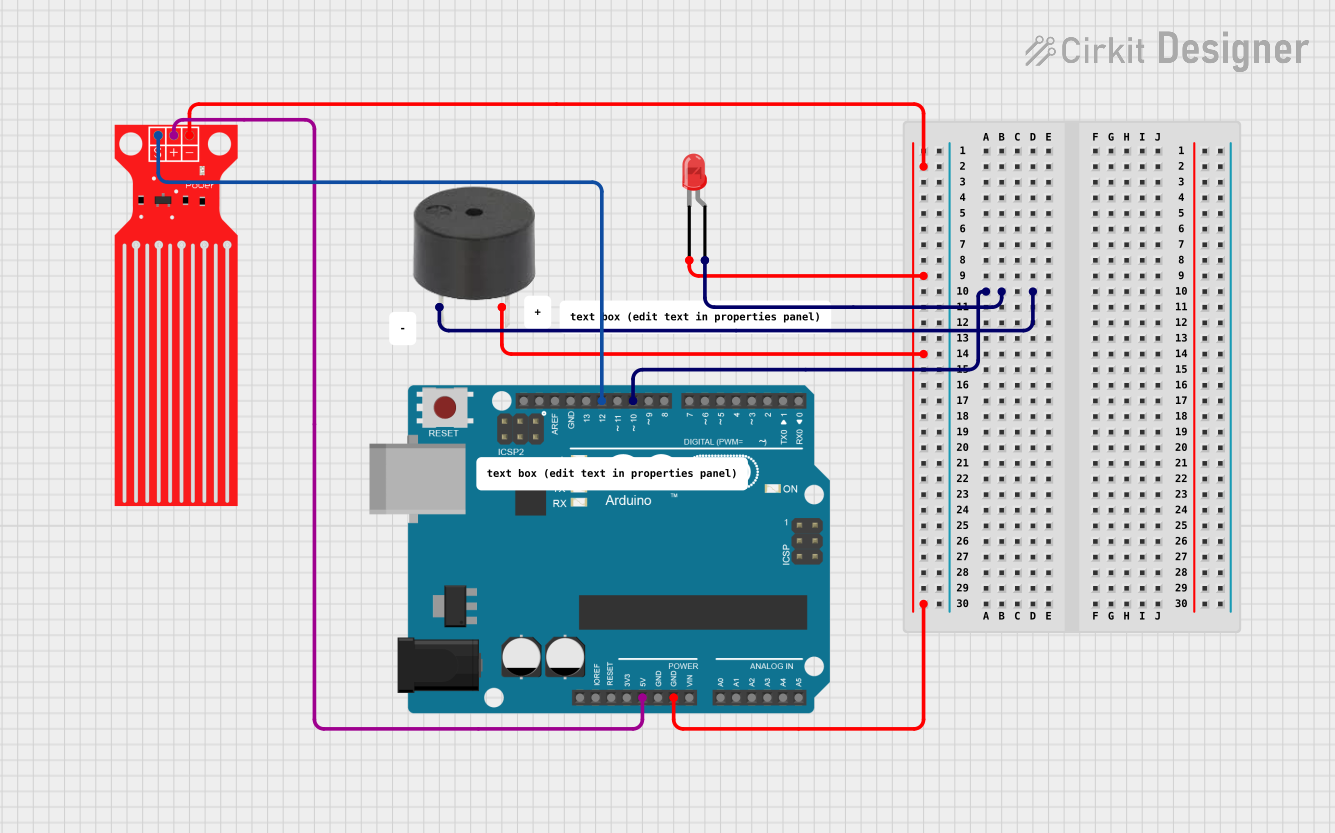
Circuit Documentation
Summary of the Circuit
This circuit is designed to monitor the water level using a water level sensor and provide visual and audible alerts when the water reaches a certain level. The core of the circuit is an Arduino UNO microcontroller, which reads the sensor data and controls a buzzer and an LED based on the water level. The buzzer and LED are activated when the water level is high, indicating a potential overflow condition.
Component List
Arduino UNO
- Description: A microcontroller board based on the ATmega328P.
- Pins: UNUSED, IOREF, Reset, 3.3V, 5V, GND, Vin, A0-A5, SCL, SDA, AREF, D0-D13.
- Purpose: Acts as the central processing unit of the circuit, reading sensor data and controlling the buzzer and LED.
Buzzer
- Description: An electromechanical component that emits sound when powered.
- Pins: PIN, GND.
- Purpose: Provides an audible alert when the water level is high.
Water Level Sensor
- Description: A sensor that detects the presence of water.
- Pins: SIG, VCC, GND.
- Purpose: Measures the water level and sends the signal to the Arduino.
LED: Two Pin (red)
- Description: A basic red light-emitting diode.
- Pins: cathode, anode.
- Purpose: Provides a visual alert when the water level is high.
Comments
- Description: Non-electrical components used for documentation purposes within the design.
Wiring Details
Arduino UNO
- GND: Connected to the GND pins of the Water Level Sensor, Buzzer, and LED.
- 5V: Provides power to the VCC pin of the Water Level Sensor.
- D10: Controls the PIN of the Buzzer and the anode of the LED.
- D12: Reads the SIG pin from the Water Level Sensor.
Buzzer
- PIN: Controlled by the D10 pin of the Arduino UNO.
- GND: Connected to the GND pin of the Arduino UNO.
Water Level Sensor
- SIG: Connected to the D12 pin of the Arduino UNO.
- VCC: Powered by the 5V pin of the Arduino UNO.
- GND: Connected to the GND pin of the Arduino UNO.
LED: Two Pin (red)
- anode: Controlled by the D10 pin of the Arduino UNO.
- cathode: Connected to the GND pin of the Arduino UNO.
Documented Code
// Define the pins for the water sensor, buzzer, and LED
const int waterSensorPin = 12;
const int buzzerPin = 10;
const int ledPin = 10;

void setup() {
  // Initialize the water sensor pin as input
  pinMode(waterSensorPin, INPUT);

  // Initialize the buzzer and LED pins as outputs
  pinMode(buzzerPin, OUTPUT);
  pinMode(ledPin, OUTPUT);
}

void loop() {
  // Read the water sensor value
  int sensorValue = digitalRead(waterSensorPin);

  // If water is detected, turn on the buzzer and LED
  if (sensorValue == HIGH) {
    digitalWrite(buzzerPin, HIGH);
    digitalWrite(ledPin, HIGH);
  } else {
    // If water is not detected, turn off the buzzer and LED
    digitalWrite(buzzerPin, LOW);
    digitalWrite(ledPin, LOW);
  }

  // Wait for 100 milliseconds before reading the sensor again
  delay(100);
}
Note: The code provided controls both the buzzer and the LED using the same pin (D10). This is likely an error, as they should be controlled independently. The code should be revised to use separate pins for the buzzer and the LED.