
Arduino 101-Based Smart Alarm Clock with Ultrasonic Sensor and IR Remote Control
View and Edit Project In Cirkit Designer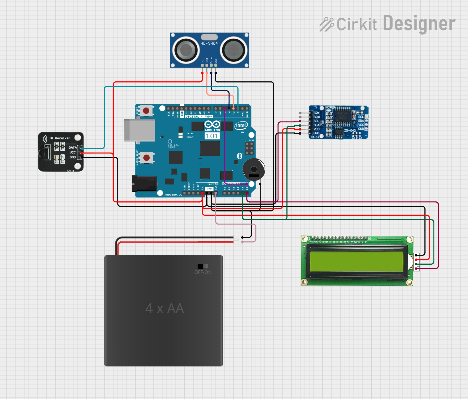
Circuit Documentation
Summary
This circuit is an alarm system that utilizes an Arduino 101 microcontroller to control various components including an LCD display, an ultrasonic sensor, a piezo buzzer, an IR receiver, and an RTC module. The system displays the current time and alarm time on the LCD, and the alarm can be set and controlled using an IR remote. The alarm is activated at a specified time and can be deactivated by moving an object within a certain distance from the ultrasonic sensor.
Component List
Arduino 101
- Description: Microcontroller board based on the Intel Curie module.
- Pins: A5/SCL, A4/SDA, AREF, GND, D13/SCK, D12/MISO, D11 PWM/MOSI, D10 PWM/SS, D9 PWM, D8, D7, D6 PWM, D5 PWM, D4, D3 PWM, D2, D1/TX, D0/RX, AIN, ioref, RESET, 3V3, 5V, VIN, A0, A1, A2, A3, ICSP MISO, ICSP SCK, ICSP MOSI
Piezo Buzzer
- Description: A small speaker that generates sound.
- Pins: pin 1, pin 2
HC-SR04 Ultrasonic Sensor
- Description: Sensor that measures distance by using ultrasonic waves.
- Pins: VCC, TRIG, ECHO, GND
MKE-M07 LCD1602 I2C
- Description: 16x2 character LCD display with I2C interface.
- Pins: GND, 5V, SDA, SCL
4xAA_JST
- Description: Battery pack with JST connector.
- Pins: POS, NEG
RTC DS3231
- Description: Real-time clock module.
- Pins: 32K, SQW, SCL, SDA, VCC, GND
IR Receiver
- Description: Infrared receiver for remote control signals.
- Pins: DATA, VCC, GND
Wiring Details
Arduino 101
- A5/SCL: Connected to SCL of MKE-M07 LCD1602 I2C and RTC DS3231
- A4/SDA: Connected to SDA of MKE-M07 LCD1602 I2C and RTC DS3231
- D5 PWM: Connected to pin 1 of Piezo Buzzer
- D4: Connected to ECHO of HC-SR04 Ultrasonic Sensor
- D3 PWM: Connected to TRIG of HC-SR04 Ultrasonic Sensor
- D2: Connected to DATA of IR Receiver
- 5V: Connected to VCC of HC-SR04 Ultrasonic Sensor, MKE-M07 LCD1602 I2C, RTC DS3231, and IR Receiver
- GND: Connected to GND of MKE-M07 LCD1602 I2C, IR Receiver, and Piezo Buzzer
- VIN: Connected to POS of 4xAA_JST
Piezo Buzzer
- pin 1: Connected to D5 PWM of Arduino 101
- pin 2: Connected to GND
HC-SR04 Ultrasonic Sensor
- VCC: Connected to 5V of Arduino 101
- TRIG: Connected to D3 PWM of Arduino 101
- ECHO: Connected to D4 of Arduino 101
- GND: Connected to NEG of 4xAA_JST
MKE-M07 LCD1602 I2C
- GND: Connected to GND of Arduino 101
- 5V: Connected to 5V of Arduino 101
- SDA: Connected to A4/SDA of Arduino 101
- SCL: Connected to A5/SCL of Arduino 101
4xAA_JST
- POS: Connected to VIN of Arduino 101
- NEG: Connected to GND of HC-SR04 Ultrasonic Sensor
RTC DS3231
- SCL: Connected to A5/SCL of Arduino 101
- SDA: Connected to A4/SDA of Arduino 101
- VCC: Connected to 5V of Arduino 101
- GND: Connected to GND of HC-SR04 Ultrasonic Sensor
IR Receiver
- DATA: Connected to D2 of Arduino 101
- VCC: Connected to 5V of Arduino 101
- GND: Connected to GND of Arduino 101
Documented Code
#include <Wire.h>
#include <LiquidCrystal_I2C.h>
#include <RTClib.h>
#include <IRremote.h>
#include <NewPing.h>

// Pin definitions
#define IR_RECEIVE_PIN 2
#define TRIGGER_PIN 3
#define ECHO_PIN 4
#define BUZZER_PIN 5

// Constants
#define MAX_DISTANCE 300 // Maximum distance to measure (in cm)
#define ALARM_DISTANCE 300 // Minimum distance to deactivate alarm (in cm)
#define POWER_BUTTON_CODE 0xFFA25D
#define VOLUME_UP_BUTTON_CODE 0xFF629D
#define VOLUME_DOWN_BUTTON_CODE 0xFFE21D

// Initialize LCD
LiquidCrystal_I2C lcd(0x27, 16, 2);

// Initialize RTC
RTC_DS1307 rtc;

// Initialize IR Receiver
IRrecv irrecv(IR_RECEIVE_PIN);
decode_results results;

// Initialize Ultrasonic Sensor
NewPing sonar(TRIGGER_PIN, ECHO_PIN, MAX_DISTANCE);

// Variables
int alarmHour = 7; // Default alarm hour
int alarmMinute = 0; // Default alarm minute
bool alarmSet = false;
bool alarmActive = false;

void setup() {
  Serial.begin(9600);
  lcd.begin();
  lcd.backlight();
  irrecv.enableIRIn(); // Start the IR receiver
  pinMode(BUZZER_PIN, OUTPUT);
  rtc.begin();
  if (!rtc.isrunning()) {
    rtc.adjust(DateTime(F(__DATE__), F(__TIME__)));
  }
}

void loop() {
  // Get current time
  DateTime now = rtc.now();

  // Display current time on LCD
  lcd.setCursor(0, 0);
  lcd.print("Time: ");
  if (now.hour() < 10) {
    lcd.print("0");
  }
  lcd.print(now.hour());
  lcd.print(":");
  if (now.minute() < 10) {
    lcd.print("0");
  }
  lcd.print(now.minute());

  // Display alarm time on LCD
  lcd.setCursor(0, 1);
  lcd.print("Alarm: ");
  if (alarmHour < 10) {
    lcd.print("0");
  }
  lcd.print(alarmHour);
  lcd.print(":");
  if (alarmMinute < 10) {
    lcd.print("0");
  }
  lcd.print(alarmMinute);

  // Check if alarm should be active
  if (now.hour() == alarmHour && now.minute() == alarmMinute && !alarmActive) {
    alarmActive = true;
    tone(BUZZER_PIN, 1000); // Sound the buzzer
  }

  // Check IR remote for alarm setting
  if (irrecv.decode(&results)) {
    handleIRInput(results.value);
    irrecv.resume(); // Receive the next value
  }

  // Check distance to deactivate alarm
  if (alarmActive) {
    int distance = sonar.ping_cm();
    if (distance > ALARM_DISTANCE) {
      noTone(BUZZER_PIN); // Stop the buzzer
      alarmActive = false;
    }
  }

  delay(1000); // Update every second
}

void handleIRInput(unsigned long value) {
  switch (value) {
    case POWER_BUTTON_CODE: // Power button
      alarmSet = !alarmSet;
      break;
    case VOLUME_UP_BUTTON_CODE: // Volume up button
      alarmHour = (alarmHour + 1) % 24;
      break;
    case VOLUME_DOWN_BUTTON_CODE: // Volume down button
      alarmMinute = (alarmMinute + 1) % 60;
      break;
    // Add more cases for other buttons as needed
  }
}
This code initializes and controls the various components connected to the Arduino 101. It sets up the LCD, RTC, IR receiver, and ultrasonic sensor, and includes logic for setting and activating the alarm. The alarm can be controlled using an IR remote, and it will deactivate when an object is detected within a specified distance by the ultrasonic sensor.