Cirkit Designer
Your all-in-one circuit design IDE
Home /
Project Documentation
Piezo-Triggered LED Indicator

Circuit Documentation
Summary of the Circuit
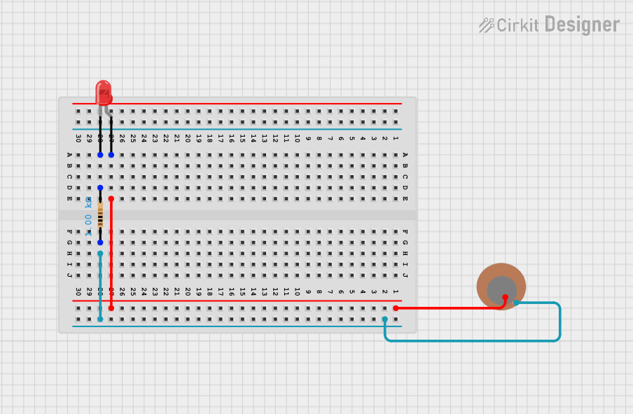
This circuit appears to be a simple sensor circuit that uses a piezo sensor to detect vibrations or pressure changes. When the piezo sensor is activated, it allows current to flow through to the anode of a red LED, causing the LED to light up. A resistor is connected in series with the LED to limit the current and protect the LED from damage due to excessive current.
Component List
LED: Two Pin (red)
- Description: A basic red LED used for indicating status or as a visual alert.
- Pins:
- Cathode: The negative terminal of the LED.
- Anode: The positive terminal of the LED.
Resistor
- Description: A resistor with a resistance value of 1000 Ohms (1 kOhm).
- Pins:
- Pin1: One terminal of the resistor.
- Pin2: The other terminal of the resistor.
- Properties:
- Resistance: 1000 Ohms
Piezo Sensor
- Description: A sensor that generates an electrical charge in response to applied mechanical stress.
- Pins:
- +: Positive terminal of the piezo sensor.
- -: Negative terminal of the piezo sensor.
Wiring Details
LED: Two Pin (red)
- Anode: Connected to the positive terminal of the Piezo Sensor.
- Cathode: Connected to Pin2 of the Resistor.
Resistor
- Pin1: Connected to the negative terminal of the Piezo Sensor.
- Pin2: Connected to the cathode of the LED: Two Pin (red).
Piezo Sensor
- +: Connected to the anode of the LED: Two Pin (red).
- -: Connected to Pin1 of the Resistor.
Documented Code
There is no microcontroller or embedded code associated with this circuit as per the provided inputs. Therefore, no code documentation is necessary for this circuit. If a microcontroller is added to the circuit in the future, the code will be documented in this section.