
ESP32-Based Solar-Powered Current Monitoring System with OLED Display
View and Edit Project In Cirkit Designer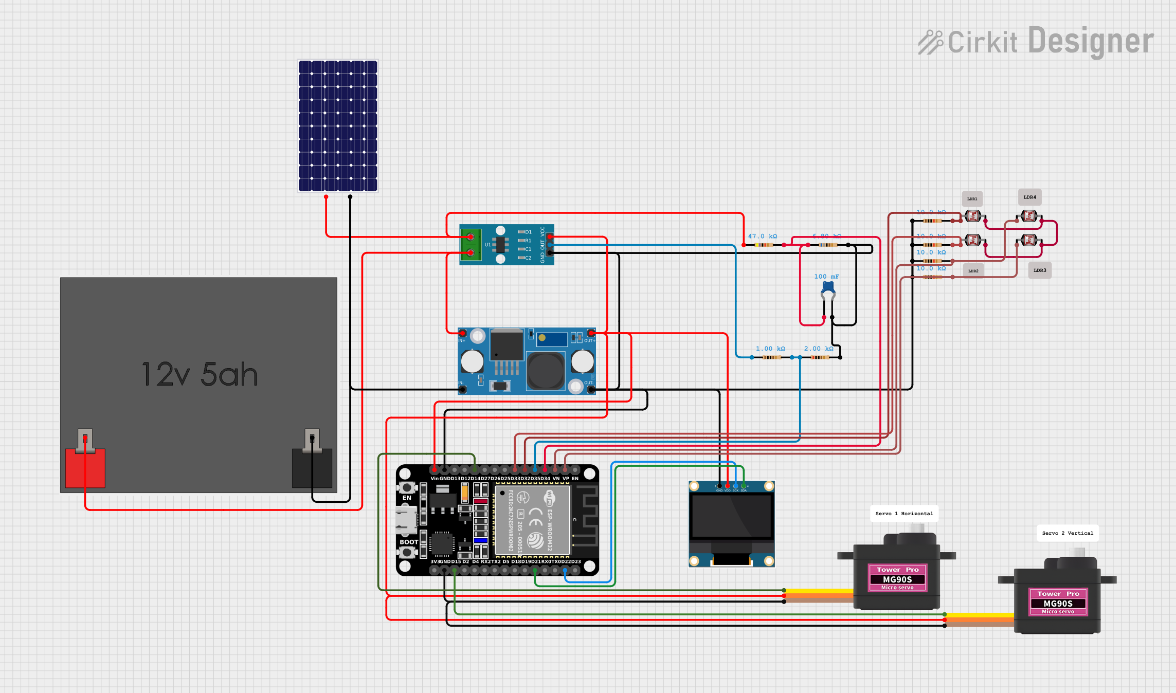
Circuit Documentation
Summary
This circuit is designed to measure current using an ACS712 Current Sensor and display the readings on a 0.96" OLED screen. It is controlled by an ESP32 microcontroller, which processes the sensor data and manages the display. The circuit is powered by a 12V 5Ah battery, which is regulated down to a lower voltage suitable for the components using an LM2596 Step Down Module. Photocells (LDRs) are included to potentially measure light intensity, and servomotors are present, possibly for actuation based on the microcontroller's logic. The circuit includes various resistors and a ceramic capacitor for stability and voltage division.
Component List
Power Supply Components
- LM2596 Step Down Module: A voltage regulator module that steps down the input voltage to a lower output voltage.
- 12v5ah Battery: A 12V battery that provides power to the circuit.
- Solar Panel: A solar panel that can charge the battery or provide power to the circuit.
Sensing and Actuation Components
- ACS712 Current Sensor 5A 20A 30A: A hall-effect-based linear current sensor capable of measuring both AC and DC currents.
- Photocell (LDR): Light-dependent resistors used for measuring light intensity.
- Servomotor MG90S: Small servomotors for precise angular movement.
Display Components
- 0.96" OLED: A small OLED display for showing information such as current measurements.
Processing Components
- ESP32 (30 pin): A microcontroller with Wi-Fi and Bluetooth capabilities, used for processing sensor data and controlling the display and other peripherals.
Passive Components
- Resistors: Various resistors used for voltage division and current limiting.
- Ceramic Capacitor: A capacitor used for noise reduction and voltage smoothing.
Wiring Details
LM2596 Step Down Module
- OUT-: Connected to the ground net, which includes GND pins of various components.
- OUT+: Connected to the positive voltage net, which includes VCC pins of various components.
- IN-: Connected to the negative terminal of the 12v5ah Battery and the negative pin of the Solar Panel.
- IN+: Connected to the positive terminal of the 12v5ah Battery and the positive pin of the Solar Panel.
0.96" OLED
- GND: Connected to the ground net.
- VDD: Connected to the positive voltage net.
- SCK: Connected to pin D22 of the ESP32.
- SDA: Connected to pin D21 of the ESP32.
ACS712 Current Sensor
- 1: Connected to the positive terminal of the Solar Panel through a resistor.
- 2: Connected to the positive terminal of the 12v5ah Battery.
- GND: Connected to the ground net.
- OUT: Connected to pin D35 of the ESP32 through a resistor.
- VCC: Connected to the positive voltage net.
Photocells (LDR)
- Pin 0: Each connected to different analog pins (VP, VN, D32, D33) of the ESP32.
- Pin 1: All connected together.
Servomotor MG90S
- SIG: Connected to pins D14 and D15 of the ESP32 for the two servomotors.
- VCC: Connected to the positive voltage net.
- GND: Connected to the ground net.
Resistors and Capacitor
- Various resistors are connected in series with LDRs and between power lines and sensor outputs. The capacitor is connected across the power supply lines for decoupling.
Documented Code
ESP32 Microcontroller Code
#include <Wire.h>
#include <Adafruit_GFX.h>
#include <Adafruit_SSD1306.h>

#define SCREEN_WIDTH 128
#define SCREEN_HEIGHT 64
#define OLED_RESET    -1
Adafruit_SSD1306 display(SCREEN_WIDTH, SCREEN_HEIGHT, &Wire, OLED_RESET);

const int currentSensorPin = 35; // Pin connected to ACS712 OUT

void setup() {
  // Initialize serial communication
  Serial.begin(115200);

  // Initialize the OLED display
  if(!display.begin(SSD1306_I2C_ADDRESS, OLED_RESET)) {
    Serial.println(F("SSD1306 allocation failed"));
    for(;;);
  }
  display.display();
  delay(2000);
  display.clearDisplay();

  // Initialize the current sensor pin
  pinMode(currentSensorPin, INPUT);
}

void loop() {
  // Read the current sensor value
  int sensorValue = analogRead(currentSensorPin);
  float voltage = sensorValue * (3.3 / 4095.0); // Convert to voltage
  float current = (voltage - 2.5) / 0.185; // Convert to current (assuming 5A sensor)

  // Display the current on the OLED
  display.clearDisplay();
  display.setTextSize(1);
  display.setTextColor(SSD1306_WHITE);
  display.setCursor(0, 0);
  display.print("Current: ");
  display.print(current);
  display.println(" A");
  display.display();

  // Print the current to the serial monitor
  Serial.print("Current: ");
  Serial.print(current);
  Serial.println(" A");

  delay(1000); // Wait for a second before the next reading
}
This code snippet is for the ESP32 microcontroller. It initializes the OLED display and reads the current sensor's output. The current is calculated from the sensor's voltage output and displayed on the OLED screen. The current value is also sent to the serial monitor for debugging purposes.