
ESP32-Based Smart Home Automation System with Ultrasonic, PIR, and DHT11 Sensors
View and Edit Project In Cirkit Designer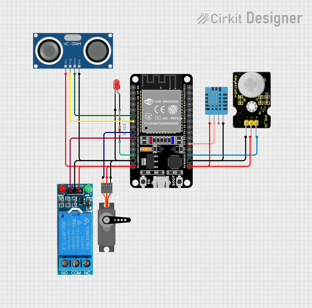
Circuit Documentation
Summary
This document provides a detailed overview of a circuit that includes various sensors, a relay, a servo motor, an LED, and an ESP32 microcontroller. The circuit is designed to interface with multiple sensors and actuators, providing a comprehensive setup for a variety of applications such as environmental monitoring and control.
Component List
Servo
- Pins: GND, VCC, PWM
- Description: A servo motor used for precise control of angular position.
- Purpose in Circuit: Actuator for mechanical movement.
HC-SR04 Ultrasonic Sensor
- Pins: VCC, TRIG, ECHO, GND
- Description: An ultrasonic sensor used for distance measurement.
- Purpose in Circuit: Distance measurement.
12V SINGLE CHANNEL RELAY
- Pins: NC, COM, NO, IN, GND, VCC
- Description: A relay used to control high voltage devices.
- Purpose in Circuit: Switch for high voltage devices.
DHT11 Humidity and Temperature Sensor
- Pins: VDD, DATA, NULL, GND
- Description: A sensor used to measure humidity and temperature.
- Purpose in Circuit: Environmental monitoring.
PIR Sensor
- Pins: GND, VCC, Data
- Description: A passive infrared sensor used for motion detection.
- Purpose in Circuit: Motion detection.
LED: Two Pin (red)
- Pins: cathode, anode
- Description: A red LED used for visual indication.
- Purpose in Circuit: Visual indicator.
ESP32 (30 pin)
- Pins: EN, VP, VN, D34, D35, D32, D33, D25, D26, D27, D14, D12, D13, GND, Vin, D23, D22, TX0, RX0, D21, D19, D18, D5, TX2, RX2, D4, D2, D15, 3V3
- Description: A microcontroller with Wi-Fi and Bluetooth capabilities.
- Purpose in Circuit: Central control unit.
Resistor
- Pins: pin1, pin2
- Description: A resistor with a resistance of 220 Ohms.
- Purpose in Circuit: Current limiting for the LED.
Wiring Details
Servo
- GND connected to ESP32 GND
- VCC connected to ESP32 Vin
- PWM connected to ESP32 D26
HC-SR04 Ultrasonic Sensor
- VCC connected to ESP32 Vin
- TRIG connected to ESP32 D33
- ECHO connected to ESP32 D32
- GND connected to ESP32 GND
12V SINGLE CHANNEL RELAY
- IN connected to ESP32 D27
- GND connected to ESP32 GND
- VCC connected to ESP32 Vin
DHT11 Humidity and Temperature Sensor
- VDD connected to ESP32 3V3
- DATA connected to ESP32 D4
- GND connected to ESP32 GND
PIR Sensor
- GND connected to ESP32 GND
- VCC connected to ESP32 3V3
- Data connected to ESP32 D15
LED: Two Pin (red)
- cathode connected to ESP32 GND
- anode connected to Resistor pin1
Resistor
- pin1 connected to LED anode
- pin2 connected to ESP32 D13
ESP32 (30 pin)
- D32 connected to HC-SR04 Ultrasonic Sensor ECHO
- D33 connected to HC-SR04 Ultrasonic Sensor TRIG
- D26 connected to Servo PWM
- D27 connected to 12V SINGLE CHANNEL RELAY IN
- D13 connected to Resistor pin2
- GND connected to 12V SINGLE CHANNEL RELAY GND, HC-SR04 Ultrasonic Sensor GND, LED cathode, Servo GND, PIR Sensor GND, DHT11 Humidity and Temperature Sensor GND
- Vin connected to 12V SINGLE CHANNEL RELAY VCC, HC-SR04 Ultrasonic Sensor VCC, Servo VCC
- D4 connected to DHT11 Humidity and Temperature Sensor DATA
- D15 connected to PIR Sensor Data
- 3V3 connected to PIR Sensor VCC, DHT11 Humidity and Temperature Sensor VDD
Code
No code provided for this circuit.
This document provides a comprehensive overview of the circuit, including a detailed list of components and their wiring connections. This should serve as a useful reference for building and troubleshooting the circuit.