
ESP8266 NodeMCU Controlled RFID Access System with I2C LCD Feedback
View and Edit Project In Cirkit Designer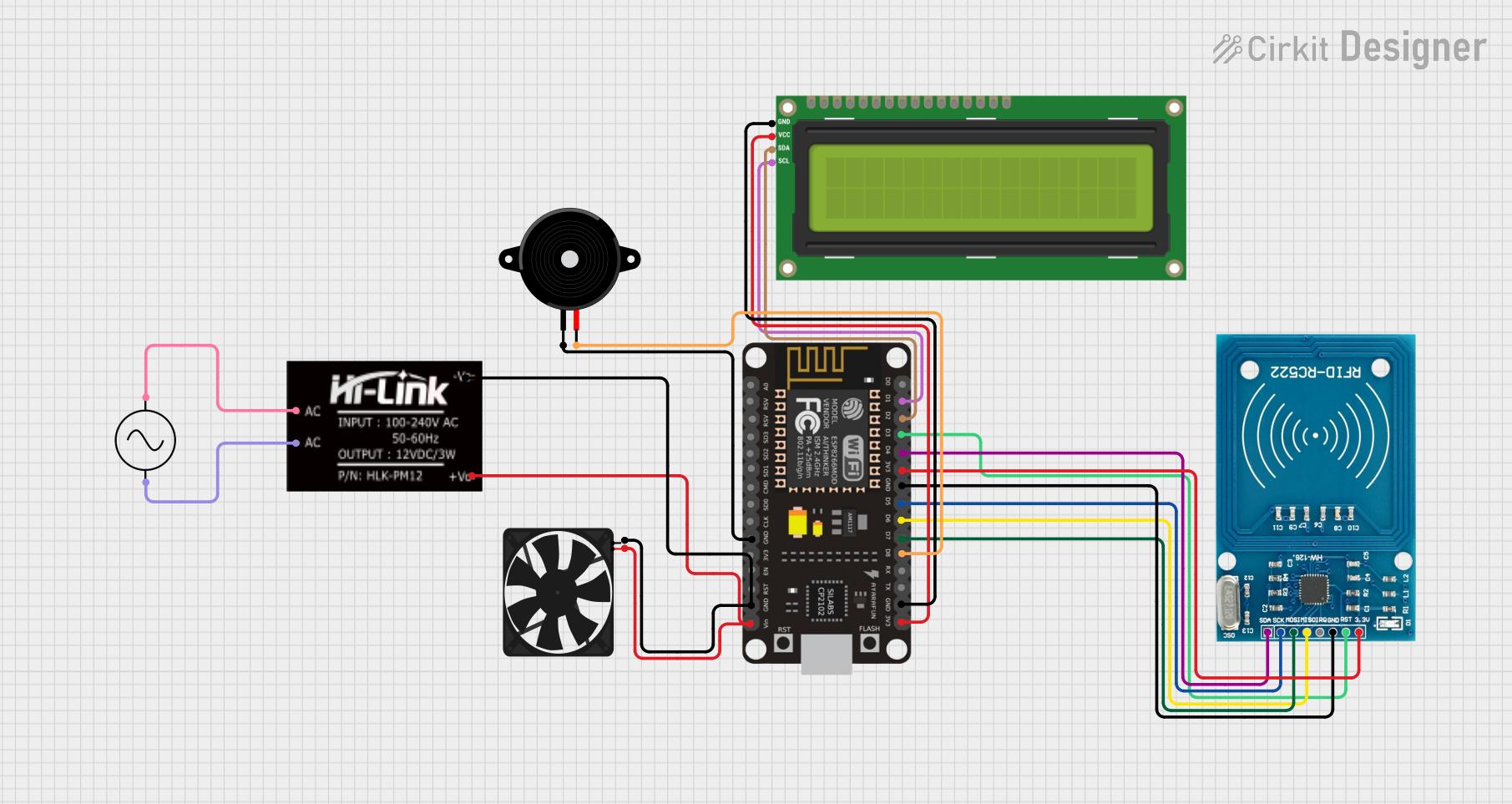
Circuit Documentation
Summary
This circuit is designed around the ESP8266 NodeMCU microcontroller, which serves as the central processing unit. The circuit features an I2C LCD 16x2 screen for display, an RFID-RC522 module for RFID reading, a piezo speaker for audio feedback, and a fan for cooling or airflow purposes. The circuit is powered by an HLK-PM12 AC-DC converter module, which steps down the AC supply to a stable DC voltage. The ESP8266 NodeMCU is programmed to connect to a WiFi network, read RFID tags, display information on the LCD, and send data to a server.
Component List
- ESP8266 NodeMCU: A WiFi-enabled microcontroller used for controlling the circuit and processing data.
- I2C LCD 16x2 Screen: A 16x2 character LCD display that uses the I2C communication protocol for displaying information.
- Piezo Speaker: An electronic device that emits sound when an electric signal is applied.
- Fan: A device powered by a DC voltage used to create airflow.
- RFID-RC522: An RFID reader/writer module that operates at 13.56 MHz.
- HLK-PM12: An AC-DC converter module that provides a regulated DC output from an AC input.
- Ac Supply: The main power source for the circuit, providing AC voltage.
Wiring Details
ESP8266 NodeMCU
- D1 (SCL): Connected to the SCL pin of the I2C LCD screen.
- D2 (SDA): Connected to the SDA pin of the I2C LCD screen.
- D3 (RST_PIN): Connected to the RST pin of the RFID-RC522 module.
- D4 (SS_PIN): Connected to the SDA pin of the RFID-RC522 module.
- 3V3: Connected to the VCC (3.3V) pin of the RFID-RC522 module and VCC (5V) pin of the I2C LCD screen.
- GND: Common ground for the ESP8266 NodeMCU, RFID-RC522 module, I2C LCD screen, piezo speaker, and fan.
- D5 (SCK): Connected to the SCK pin of the RFID-RC522 module.
- D6 (MISO): Connected to the MISO pin of the RFID-RC522 module.
- D7 (MOSI): Connected to the MOSI pin of the RFID-RC522 module.
- D8 (BUZZER_PIN): Connected to pin2 of the piezo speaker.
- VIN: Connected to the +V0 output of the HLK-PM12 module.
I2C LCD 16x2 Screen
- SCL: Connected to the D1 pin of the ESP8266 NodeMCU.
- SDA: Connected to the D2 pin of the ESP8266 NodeMCU.
- VCC (5V): Connected to the 3V3 pin of the ESP8266 NodeMCU.
- GND: Connected to the common ground.
Piezo Speaker
- pin1: Connected to the common ground.
- pin2: Connected to the D8 pin of the ESP8266 NodeMCU.
Fan
- GND: Connected to the common ground.
- 5V: Connected to the +V0 output of the HLK-PM12 module.
RFID-RC522
- VCC (3.3V): Connected to the 3V3 pin of the ESP8266 NodeMCU.
- RST: Connected to the D3 pin of the ESP8266 NodeMCU.
- GND: Connected to the common ground.
- IRQ: Not connected.
- MISO: Connected to the D6 pin of the ESP8266 NodeMCU.
- MOSI: Connected to the D7 pin of the ESP8266 NodeMCU.
- SCK: Connected to the D5 pin of the ESP8266 NodeMCU.
- SDA: Connected to the D4 pin of the ESP8266 NodeMCU.
HLK-PM12
- +V0: Connected to the VIN pin of the ESP8266 NodeMCU and the 5V pin of the fan.
- -V0: Connected to the common ground.
- AC: Connected to both the +ve and -ve pins of the Ac Supply.
Ac Supply
- +ve: Connected to the AC pin of the HLK-PM12 module.
- -ve: Connected to the AC pin of the HLK-PM12 module.
Documented Code
The following code is written for the ESP8266 NodeMCU microcontroller. It includes libraries for WiFi connectivity, HTTP client for server communication, SPI for serial peripheral interface communication, Wire for I2C communication, and libraries for the LCD and RFID modules.
#include <ESP8266WiFi.h>
#include <ESP8266HTTPClient.h>
#include <MFRC522.h>
#include <SPI.h>
#include <Wire.h>
#include <hd44780.h>          // main hd44780 header
#include <hd44780ioClass/hd44780_I2Cexp.h>

#define RST_PIN   D3     // Reset pin for MFRC522
#define SS_PIN    D4     // Slave Select pin for MFRC522
#define BUZZER_PIN D8    // Buzzer pin

MFRC522 mfrc522(SS_PIN, RST_PIN); // Create MFRC522 instance
hd44780_I2Cexp lcd;

// WiFi credentials
const char* ssid = "MVGR_SLC";
const char* password = "001010011100";

void setup() {
  Serial.begin(9600);
  SPI.begin();
  lcd.begin(16, 2);  // Initialize 16x2 LCD
  lcd.backlight();
  mfrc522.PCD_Init();
  WiFi.begin(ssid, password);

  while (WiFi.status() != WL_CONNECTED) {
    delay(1000);
    Serial.println("Connecting to WiFi...");
    lcd.print("Connecting....");
  }

  Serial.println("Connected to WiFi");
  Serial.println("All setup done");
  lcd.clear();
  lcd.setCursor(0, 0);
  lcd.print("Connected To");
  lcd.setCursor(0, 1);
  lcd.print(ssid);
  delay(3000);
  lcd.clear();
  getcount();
}

void loop() {
  // WiFi connection check and RFID reading
  // HTTP POST requests to server
  // LCD and buzzer feedback based on server response
  // Error handling with buzzer and LCD messages
}

// Additional functions for HTTP requests and server communication
// getcount2(), getcount(), sendSensorDataToServer()
The code is structured to initialize the hardware components in the setup() function and to continuously check for RFID cards and send data to the server in the loop() function. It also includes error handling and user feedback through the LCD and buzzer. The actual HTTP request functions (getcount2(), getcount(), sendSensorDataToServer()) are implemented to communicate with a specific server endpoint and handle the server's response.