
Arduino Nano Wireless Communication System with OLED Feedback
View and Edit Project In Cirkit Designer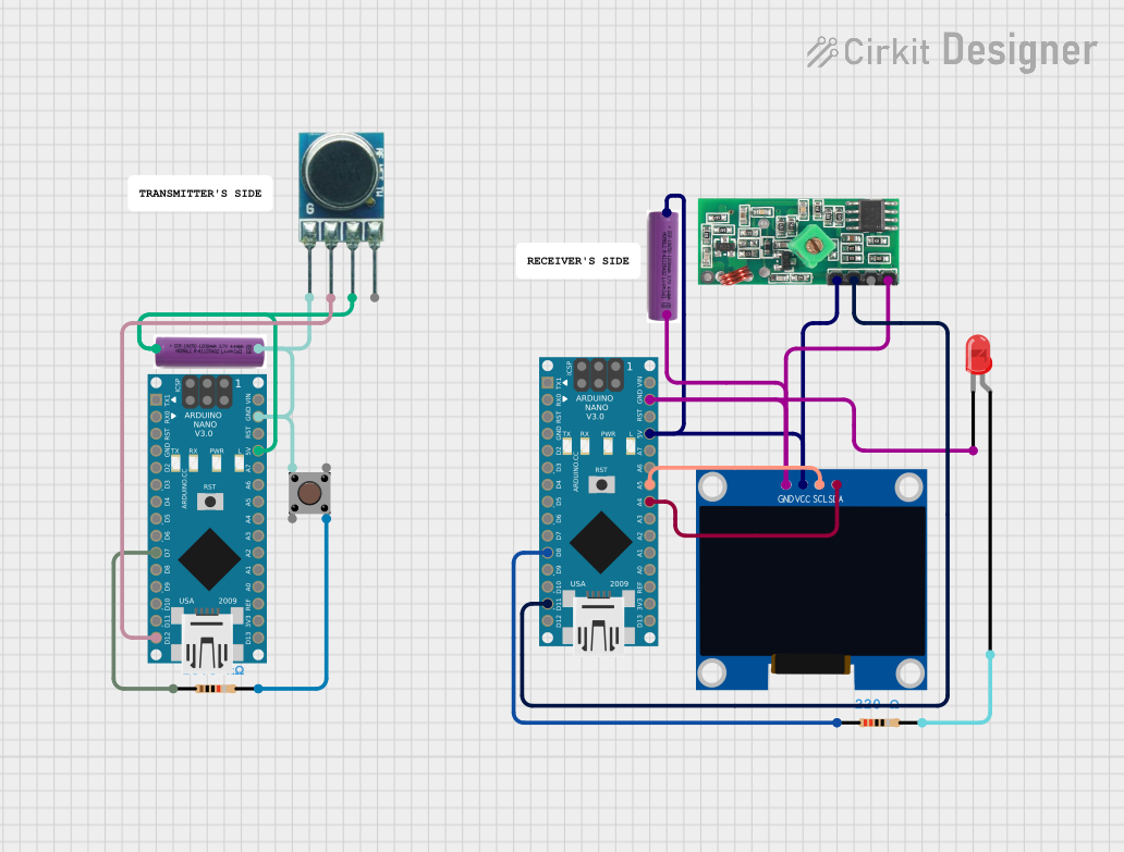
Circuit Documentation
Summary
The circuit in question appears to be a communication system utilizing Arduino Nano microcontrollers, a 433MHz RF transmitter and receiver module, an OLED display, and an LED indicator. The system is powered by 3.7v batteries. The Arduino Nanos are responsible for controlling the flow of data, interfacing with the OLED display, and managing the state of the LED through a pushbutton. The RF modules facilitate wireless communication. The resistors are used to limit current to the LED and to provide pull-up or pull-down resistors for the pushbutton.
Component List
Microcontrollers
- Arduino Nano: A compact microcontroller board based on the ATmega328P, featuring digital and analog I/O pins.
Indicators
- LED: Two Pin (red): A red light-emitting diode used as an indicator.
Power Supplies
- 3.7v battery: Provides power to the circuit.
Passive Components
- Resistor (220 Ohms): Limits current to protect components such as LEDs.
- Resistor (10k Ohms): Commonly used as a pull-up or pull-down resistor.
Display Modules
- 128x64 OLED Display (I2C IIC SPI Serial): A small display for visual output.
Communication Modules
- 433MHz RF Transmitter: Sends data wirelessly at 433MHz.
- 433 MHz RF Receiver Module: Receives data wirelessly at 433MHz.
Input Devices
- Pushbutton: An input device that allows the user to interact with the circuit.
Wiring Details
Arduino Nano
- Digital Pins: Used for interfacing with various components such as the pushbutton, RF modules, and the OLED display.
- Analog Pins: Utilized for I2C communication with the OLED display.
- Power Pins (5V and GND): Provide power to the circuit and establish a common ground.
LED: Two Pin (red)
- Anode: Connected to a 220 Ohm resistor, which is then connected to an Arduino Nano digital pin.
- Cathode: Connected to the ground.
3.7v battery
- Positive (+): Supplies power to the Arduino Nano, RF modules, and the OLED display.
- Negative (-): Connected to the ground of the circuit.
Resistor (220 Ohms)
- One Pin: Connected to the anode of the LED.
- Other Pin: Connected to a digital pin on the Arduino Nano.
Resistor (10k Ohms)
- One Pin: Connected to a digital pin on the Arduino Nano.
- Other Pin: Connected to one side of the pushbutton.
128x64 OLED Display (I2C IIC SPI Serial)
- GND: Connected to the ground.
- VCC: Powered by the 3.7v battery.
- SDA: Connected to the corresponding SDA pin on the Arduino Nano.
- SCL: Connected to the corresponding SCL pin on the Arduino Nano.
433MHz RF Transmitter
- GND: Connected to the ground.
- Data In: Connected to a digital pin on the Arduino Nano.
- VCC: Powered by the 3.7v battery.
433 MHz RF Receiver Module
- GND: Connected to the ground.
- DATA: Connected to a digital pin on the Arduino Nano.
- VCC: Powered by the 3.7v battery.
Pushbutton
- Pin 1 (in): Connected to the ground.
- Pin 4 (out): Connected to a 10k Ohm resistor, which is then connected to a digital pin on the Arduino Nano.
Documented Code
Arduino Nano (Primary Controller)
void setup() {
  // put your setup code here, to run once:

}

void loop() {
  // put your main code here, to run repeatedly:

}
Arduino Nano (Secondary Controller)
void setup() {
  // put your setup code here, to run once:

}

void loop() {
  // put your main code here, to run repeatedly:

}
Note: The provided code for both Arduino Nanos is a template with no specific functionality. The actual implementation should include initialization of I/O pins, setup for I2C communication, and logic for handling the pushbutton input and RF communication.