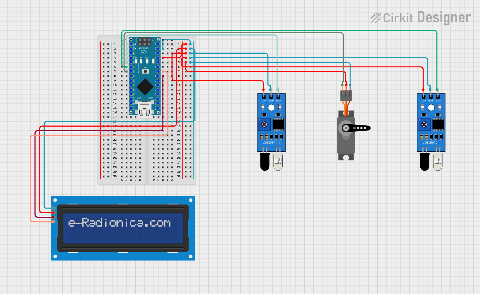
Arduino Nano Controlled LCD Display with Dual IR Sensor Inputs and Servo Output

Circuit Documentation
Summary of the Circuit
This circuit integrates an Arduino Nano microcontroller with an LCD screen (16x2 characters) using I2C communication, two IR sensors, and a servo motor. The Arduino Nano serves as the central processing unit, controlling the LCD screen to display messages, reading signals from the IR sensors, and driving the servo motor based on the program logic. The IR sensors are used to detect objects or motion, and the servo motor is controlled via PWM signal from the Arduino Nano.
Component List
Arduino Nano
- Microcontroller board based on the ATmega328P
- It has a variety of digital and analog I/O pins
- Capable of I2C, UART, and PWM outputs
LCD screen 16x2 I2C
- Alphanumeric liquid crystal display
- 16 characters wide, 2 rows
- I2C communication interface for reduced pin usage
IR Sensor
- Infrared sensor for object detection
- Outputs a digital signal when an object is detected
- Requires power (VCC) and ground (GND) connections
Servo
- Rotary actuator or motor for precise control of angular position
- Controlled via PWM signal
- Requires power (VCC) and ground (GND) connections
Wiring Details
Arduino Nano
- GND connected to the ground of all other components
- 5V provides power to VCC of all other components
- D2 connected to the output of the first IR sensor
- D3 connected to the output of the second IR sensor
- D4 connected to the PWM input of the Servo
- A4 (SDA) connected to the SDA pin of the LCD screen
- A5 (SCL) connected to the SCL pin of the LCD screen
LCD screen 16x2 I2C
- SCL connected to A5 on the Arduino Nano
- SDA connected to A4 on the Arduino Nano
- VCC connected to 5V on the Arduino Nano
- GND connected to GND on the Arduino Nano
IR Sensor
- out of the first IR sensor connected to D2 on the Arduino Nano
- out of the second IR sensor connected to D3 on the Arduino Nano
- vcc connected to 5V on the Arduino Nano
- gnd connected to GND on the Arduino Nano
Servo
- PWM connected to D4 on the Arduino Nano
- VCC connected to 5V on the Arduino Nano
- GND connected to GND on the Arduino Nano
Documented Code
Arduino Nano Code (sketch.ino)
#include "LCDIC2.h"

LCDIC2 lcd(0x27, 16, 2);

void setup() {
  if (lcd.begin()) lcd.print("Hello, World!");
}

void loop() {
  for (uint8_t i = 0; i < 15; i++) {
    lcd.setCursor(i, 1);
    delay(250);
  }
  for (uint8_t i = 15; i > 0; i--) {
    lcd.setCursor(i, 1);
    delay(250);
  }
}
This code initializes an LCD screen with I2C communication, prints "Hello, World!" on the screen, and then creates a simple animation by moving the cursor back and forth across the second row of the LCD. The LCDIC2 library is used for interfacing with the LCD, and the address 0x27 is specified for the I2C communication. The setup() function initializes the LCD and prints the initial message. The loop() function creates the animation effect by moving the cursor position and introducing a delay between movements.