Cirkit Designer
Your all-in-one circuit design IDE
Home /
Project Documentation
Raspberry Pi Pico-Controlled Robot with Ultrasonic Navigation and Light Sensing

Circuit Documentation
Summary
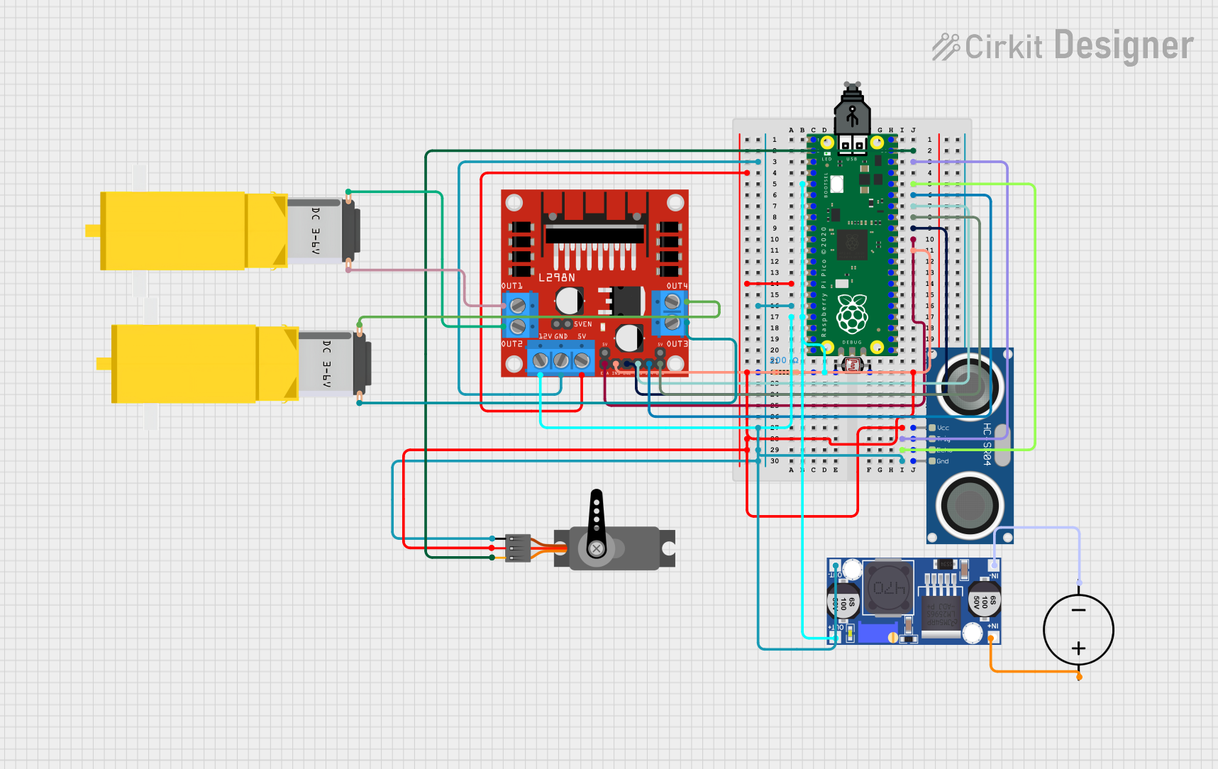
This circuit integrates a Raspberry Pi Pico microcontroller with various sensors and actuators to perform a range of functions. The Raspberry Pi Pico serves as the central processing unit, interfacing with an HC-SR04 Ultrasonic Sensor, a Photocell (LDR) with a resistor for light detection, a servo motor for precise angular movement, and two gearmotors controlled by an L298N DC motor driver. Power management is handled by a USB power source, a DC power source, and a Buck converter to step down voltage as needed. The circuit is designed to interact with the physical environment, likely for automation or robotics applications.
Component List
Raspberry Pi Pico
- Microcontroller board with a wide range of GPIO pins.
- Used as the main processing unit of the circuit.
Photocell (LDR)
- A light-dependent resistor that changes resistance based on light intensity.
- Used for sensing ambient light levels.
Resistor
- A 200 Ohm resistor.
- Used in conjunction with the Photocell (LDR) to form a voltage divider for light level measurement.
HC-SR04 Ultrasonic Sensor
- A sensor that measures distance using ultrasonic waves.
- Used for detecting objects or measuring the distance to them.
Gearmotor DC / Motorreductor
- A DC motor with a gearbox for increased torque.
- Used for driving mechanical parts.
Servo
- A motor capable of precise control of angular position.
- Used for precise positioning tasks.
USB Power
- A power source that provides power through a USB connection.
- Used to power the Raspberry Pi Pico and possibly other components.
L298N DC Motor Driver
- A motor driver capable of controlling up to two DC motors.
- Used for controlling the direction and speed of the gearmotors.
Buck Converter
- A DC-DC converter that steps down voltage.
- Used to provide the appropriate voltage levels to various components from a higher voltage source.
DC Power Source
- A source of DC power.
- Used to supply power to the circuit.
Wiring Details
Raspberry Pi Pico
pin 39connected to Servo (PWM signal)pin 38connected to HC-SR04 Ultrasonic Sensor (TRIG)pin 17connected to Photocell (LDR) and Resistor (forming a voltage divider)pin 5connected to Buck converter (power distribution)pin 36connected to HC-SR04 Ultrasonic Sensor (ECHO)pin 35,pin 34,pin 33,pin 32,pin 31,pin 30connected to L298N DC motor driver (motor control signals)
Photocell (LDR)
- One pin connected to Raspberry Pi Pico (for light level measurement)
- Other pin connected to Resistor and power supply via Buck converter
Resistor
- One pin connected to Photocell (LDR)
- Other pin connected to Raspberry Pi Pico (for light level measurement)
HC-SR04 Ultrasonic Sensor
- TRIG pin connected to Raspberry Pi Pico (trigger signal)
- ECHO pin connected to Raspberry Pi Pico (echo signal)
- VCC pin connected to power supply via Buck converter
- GND pin connected to common ground
Gearmotor DC / Motorreductor
- Connected to L298N DC motor driver (motor control)
Servo
- PWM pin connected to Raspberry Pi Pico (control signal)
- VCC pin connected to power supply via Buck converter
- GND pin connected to common ground
L298N DC Motor Driver
- IN1, IN2, IN3, IN4, ENA, ENB pins connected to Raspberry Pi Pico (motor control signals)
- OUT1, OUT2, OUT3, OUT4 pins connected to Gearmotors (motor outputs)
- 12V and 5V pins connected to power supply via Buck converter
- GND pin connected to common ground
Buck Converter
- IN+ and IN- connected to DC Power Source
- OUT+ and OUT- connected to Raspberry Pi Pico and other components requiring power
DC Power Source
- Positive and Ground pins connected to Buck converter (power input)
Documented Code
Raspberry Pi Pico (sketch.ino)
void setup() {
  // put your setup code here, to run once:

}

void loop() {
  // put your main code here, to run repeatedly:

}
Additional Notes
- The provided code for the Raspberry Pi Pico is a template with empty setup and loop functions. Actual implementation code is required for the circuit to perform specific tasks.
- The documentation file for the Raspberry Pi Pico is empty and does not contain additional information.