Arduino-Controlled Dual Relay Heating System with Temperature Sensing

Circuit Documentation
Summary
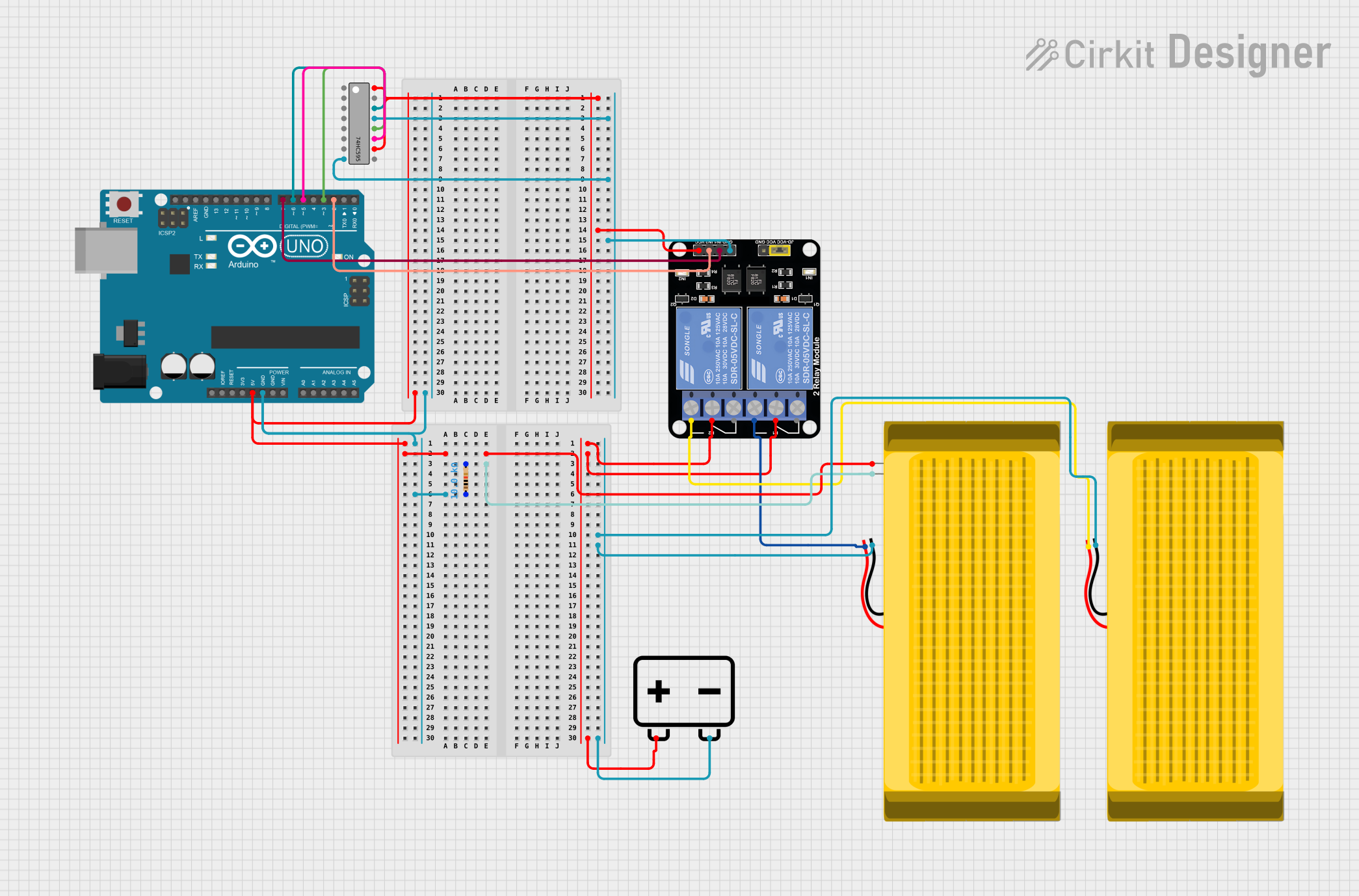
The circuit in question appears to be designed for controlling heating pads via relay modules, with an Arduino UNO as the central microcontroller. The circuit includes a shift register (74HC595) for expanding the digital outputs of the Arduino, a relay module to switch higher voltage loads, a thermistor (NTC) for temperature sensing, and two heating pads. A 12v battery is used to power the heating pads, while the Arduino and other ICs are powered by lower voltages.
Component List
Arduino UNO
- Microcontroller board based on the ATmega328P
- Provides digital I/O pins, analog inputs, and various power outputs
12v Battery
- Power source for the heating pads
- Provides a voltage of 12 volts
74HC595 Shift Register
- 8-bit serial-in, parallel-out shift register
- Expands the number of digital outputs from the Arduino
Relay Module 2 Channel
- Module with two independent relay channels
- Allows for controlling high power devices like heating pads
NTC (Negative Temperature Coefficient) Thermistor
- A resistor whose resistance decreases with increasing temperature
- Used for temperature sensing in the circuit
SparkFun Heating Pad (x2)
- Flexible heating pads for generating heat
- Powered by the 12v battery through the relay module
Resistor
- A passive two-terminal electrical component
- Used in the circuit with a value of 10,000 Ohms
Wiring Details
Arduino UNO
5Vpin connected to the NTC thermistorGNDpin connected to a 10k Ohm resistor- Digital pins
D7,D6,D5,D3, andD2connected to the relay module and 74HC595 shift register
12v Battery
+terminal connected to the common (COM) pins of the relay module-terminal connected to the heating pads
74HC595 Shift Register
MR (SRCLR)andVCCpins connected to the VCC of the relay moduleOE (Enable)andGNDpins connected to the GND of the relay moduleDS (DATA),SH_CP (SRCLK), andST_CP (RCLK)pins connected to Arduino digital pinsD6,D5, andD3respectively
Relay Module 2 Channel
VCCandGNDpins connected to the 74HC595 shift registerIN1andIN2pins connected to Arduino digital pinsD7andD2NO1andNO2pins connected to the heating pads
NTC Thermistor
- One pin connected to the
5Vpin of the Arduino - The other pin connected to a 10k Ohm resistor
SparkFun Heating Pad
- Connected to the
-terminal of the 12v battery and the normally open (NO) contacts of the relay module
Resistor
- One pin connected to the
GNDpin of the Arduino - The other pin connected to the NTC thermistor
Documented Code
void setup() {
  // put your setup code here, to run once:

}

void loop() {
  // put your main code here, to run repeatedly:

}
The provided code is a template with empty setup() and loop() functions, which are the standard structure for Arduino sketches. The setup() function is intended to contain initialization code that runs once when the microcontroller is powered on or reset. The loop() function is for code that runs continuously as long as the Arduino is powered.
Further implementation details would be required to provide a functional sketch that interacts with the hardware components as described in the wiring details. This would typically involve setting pin modes in the setup() function and controlling the pins in the loop() function to read sensors, drive the shift register, and activate the relays.