Cirkit Designer
Your all-in-one circuit design IDE
Home /
Project Documentation
Arduino Nano-Controlled LDR-Triggered AC Light Switch
Circuit Documentation
Summary
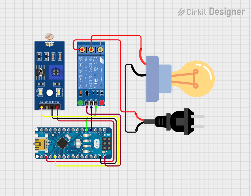
This circuit integrates an Arduino Nano microcontroller with a KF-301 relay module, an LDR (Light Dependent Resistor), and an LED bulb designed for AC power. The Arduino Nano controls the relay based on the input from the LDR, which in turn switches the LED bulb on or off. The AC source provides power to the LED bulb through the relay.
Component List
Arduino Nano
- Microcontroller board based on the ATmega328P
- It has a variety of digital and analog I/O pins
- Used for controlling the relay and reading the LDR sensor
KF-301 Relay
- A relay module that allows for controlling high power devices
- It has a signal pin to receive control signals, power and ground pins for operation, and NO, NC, and C pins for switching
LDR (Light Dependent Resistor)
- A sensor that changes resistance based on the ambient light level
- It is used to detect the light intensity in the environment
LED Bulb AC / Bombillo AC
- An LED bulb designed to operate with AC power
- It is the load controlled by the relay in response to the LDR input
AC Source
- Provides the AC power required for the LED bulb
Wiring Details
Arduino Nano
- GND connected to the ground pins of the KF-301 Relay and LDR
- D2 connected to the signal pin of the KF-301 Relay
- VIN connected to the power pin of the KF-301 Relay
- A0 connected to the A0 pin of the LDR
- 3V3 connected to the VCC pin of the LDR
KF-301 Relay
- Ground connected to the GND pin of the Arduino Nano
- Signal connected to the D2 pin of the Arduino Nano
- Power connected to the VIN pin of the Arduino Nano
- NC connected to the "+" pin of the AC source
- C connected to the "+" pin of the LED bulb AC
- NO not connected in this circuit
LDR
- GND connected to the GND pin of the Arduino Nano
- A0 connected to the A0 pin of the Arduino Nano
- VCC connected to the 3V3 pin of the Arduino Nano
LED Bulb AC / Bombillo AC
- + connected to the "C" pin of the KF-301 Relay
- - connected to the "-" pin of the AC source
AC Source
- + connected to the "NC" pin of the KF-301 Relay
- - connected to the "-" pin of the LED bulb AC
Documented Code
Arduino Nano Code (sketch.ino)
void setup() {
  // put your setup code here, to run once:

}

void loop() {
  // put your main code here, to run repeatedly:

}
Additional Notes (documentation.txt)
No additional code documentation provided.