
ESP32-Controlled Missile Launching System with L298N Motor Driver and Servo
View and Edit Project In Cirkit Designer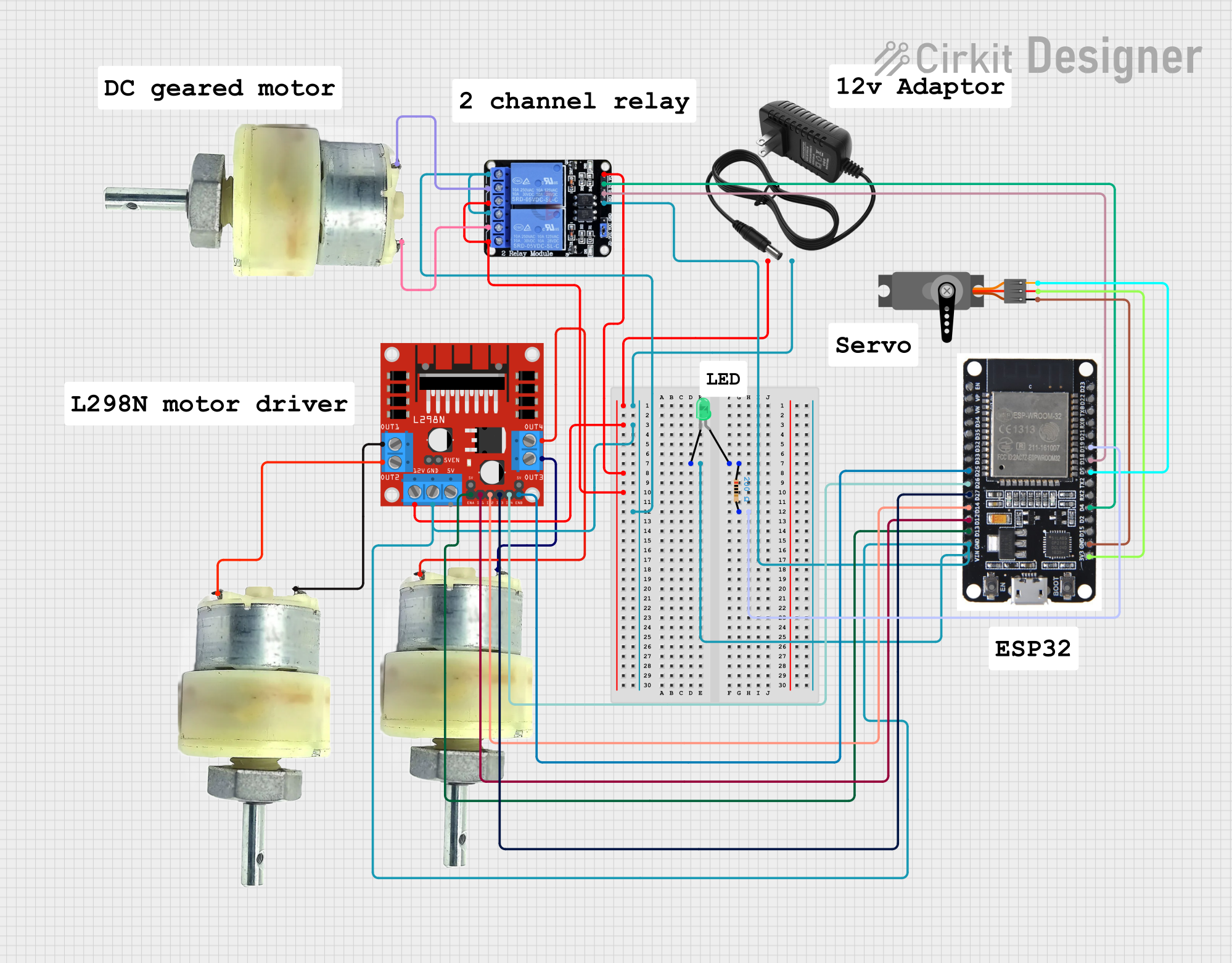
Circuit Documentation
Summary
This circuit is designed to control a missile launching system. It includes components for managing the rotation and elevation of the base, a rack-and-pinion mechanism for pulling the missile, and a servo motor for launching. An LED indicator signals readiness for launch. The system is controlled by an ESP32 microcontroller.
Component List
L298N DC Motor Driver
- Description: Dual H-Bridge motor driver for controlling DC motors.
- Pins: OUT1, OUT2, 12V, GND, 5V, OUT3, OUT4, 5V-ENA-JMP-I, 5V-ENA-JMP-O, +5V-J1, +5V-J2, ENA, IN1, IN2, IN3, IN4, ENB
12V Power Supply
- Description: Provides 12V power to the circuit.
- Pins: +, -
12V Geared Motor
- Description: DC motor with a gearbox for increased torque.
- Pins: Terminal 1, Terminal 2
Two Channel Relay 5V
- Description: Relay module for switching high-power devices.
- Pins: VCC, IN2, IN1, GND, NC2, C2, NO2, NC1, C1, NO1
ESP32
- Description: Microcontroller with Wi-Fi and Bluetooth capabilities.
- Pins: EN, VP, VN, D34, D35, D32, D33, D25, D26, D27, D14, D12, D13, GND, VIN, 3V3, D15, D2, D4, RX2, TX2, D5, D18, D19, D21, RX0, TX0, D22, D23, BOOT
Servo
- Description: Servo motor for precise control of angular position.
- Pins: GND, VCC, PWM
LED: Two Pin (green)
- Description: Green LED for indicating system status.
- Pins: cathode, anode
Resistor
- Description: 200 Ohms resistor.
- Pins: pin1, pin2
Wiring Details
L298N DC Motor Driver
- 12V connected to + of 12V Power Supply
- GND connected to GND of ESP32, GND of Two Channel Relay 5V, - of 12V Power Supply, and cathode of LED
- ENA connected to D13 of ESP32
- IN1 connected to D12 of ESP32
- IN2 connected to D14 of ESP32
- IN3 connected to D27 of ESP32
- IN4 connected to D26 of ESP32
- ENB connected to D25 of ESP32
- OUT1 connected to Terminal 1 of 12V Geared Motor
- OUT2 connected to Terminal 2 of 12V Geared Motor
- OUT3 connected to Terminal 1 of another 12V Geared Motor
- OUT4 connected to Terminal 2 of another 12V Geared Motor
12V Power Supply
- + connected to 12V of L298N DC Motor Driver and VCC of Two Channel Relay 5V
- - connected to GND of L298N DC Motor Driver, GND of ESP32, GND of Two Channel Relay 5V, and cathode of LED
12V Geared Motor
- Terminal 1 connected to OUT1 of L298N DC Motor Driver
- Terminal 2 connected to OUT2 of L298N DC Motor Driver
- Terminal 1 of another motor connected to OUT3 of L298N DC Motor Driver
- Terminal 2 of another motor connected to OUT4 of L298N DC Motor Driver
- Terminal 1 of another motor connected to C1 of Two Channel Relay 5V
- Terminal 2 of another motor connected to C2 of Two Channel Relay 5V
Two Channel Relay 5V
- VCC connected to + of 12V Power Supply
- GND connected to GND of ESP32, GND of L298N DC Motor Driver, and - of 12V Power Supply
- IN1 connected to D18 of ESP32
- IN2 connected to D4 of ESP32
- C1 connected to Terminal 1 of 12V Geared Motor
- C2 connected to Terminal 2 of 12V Geared Motor
- NC1 connected to GND
- NC2 connected to GND
- NO1 connected to + of 12V Power Supply
- NO2 connected to + of 12V Power Supply
ESP32
- GND connected to GND of L298N DC Motor Driver, GND of Two Channel Relay 5V, - of 12V Power Supply, and cathode of LED
- 3V3 connected to VCC of Servo
- D19 connected to pin2 of Resistor
- D25 connected to ENB of L298N DC Motor Driver
- D26 connected to IN4 of L298N DC Motor Driver
- D27 connected to IN3 of L298N DC Motor Driver
- D14 connected to IN2 of L298N DC Motor Driver
- D12 connected to IN1 of L298N DC Motor Driver
- D13 connected to ENA of L298N DC Motor Driver
- D4 connected to IN2 of Two Channel Relay 5V
- D5 connected to PWM of Servo
- D18 connected to IN1 of Two Channel Relay 5V
Servo
- VCC connected to 3V3 of ESP32
- GND connected to GND of ESP32
- PWM connected to D5 of ESP32
LED: Two Pin (green)
- cathode connected to GND of ESP32, GND of L298N DC Motor Driver, GND of Two Channel Relay 5V, and - of 12V Power Supply
- anode connected to pin1 of Resistor
Resistor
- pin1 connected to anode of LED
- pin2 connected to D19 of ESP32
Code Documentation
/*
 * This Arduino Sketch controls a missile launching system.
 * It manages the rotation and elevation of the base, the rack-and-pinion
 * mechanism for pulling the missile, and the servo motor for launching.
 * An LED indicator signals readiness for launch.
 */

// Pin definitions
const int motorBaseENA = 13;
const int motorBaseIN1 = 12;
const int motorBaseIN2 = 14;
const int motorElevIN3 = 27;
const int motorElevIN4 = 26;
const int motorElevENB = 25;
const int relayIN1 = 18;
const int relayIN2 = 4;
const int ledPin = 19;
const int servoPin = 5;

#include <Servo.h>
Servo servo;

void setup() {
  // Initialize pins
  pinMode(motorBaseENA, OUTPUT);
  pinMode(motorBaseIN1, OUTPUT);
  pinMode(motorBaseIN2, OUTPUT);
  pinMode(motorElevIN3, OUTPUT);
  pinMode(motorElevIN4, OUTPUT);
  pinMode(motorElevENB, OUTPUT);
  pinMode(relayIN1, OUTPUT);
  pinMode(relayIN2, OUTPUT);
  pinMode(ledPin, OUTPUT);
  servo.attach(servoPin);

  // Start the system
  digitalWrite(motorBaseENA, HIGH);
  digitalWrite(motorBaseIN1, HIGH);
  digitalWrite(motorBaseIN2, LOW);
  delay(1000); // Rotate base for 1 second
  digitalWrite(motorBaseIN1, LOW);
  digitalWrite(motorBaseIN2, LOW);

  // Adjust elevation
  digitalWrite(motorElevENB, HIGH);
  digitalWrite(motorElevIN3, HIGH);
  digitalWrite(motorElevIN4, LOW);
  delay(1000); // Adjust elevation for 1 second
  digitalWrite(motorElevIN3, LOW);
  digitalWrite(motorElevIN4, LOW);

  // Engage rack-and-pinion
  digitalWrite(relayIN1, HIGH);
  delay(1000); // Pull missile for