Cirkit Designer
Your all-in-one circuit design IDE
Home /
Project Documentation
Arduino-Controlled Multi-Stage Coin-Operated Car Wash System with LCD Display
Circuit Documentation
Summary
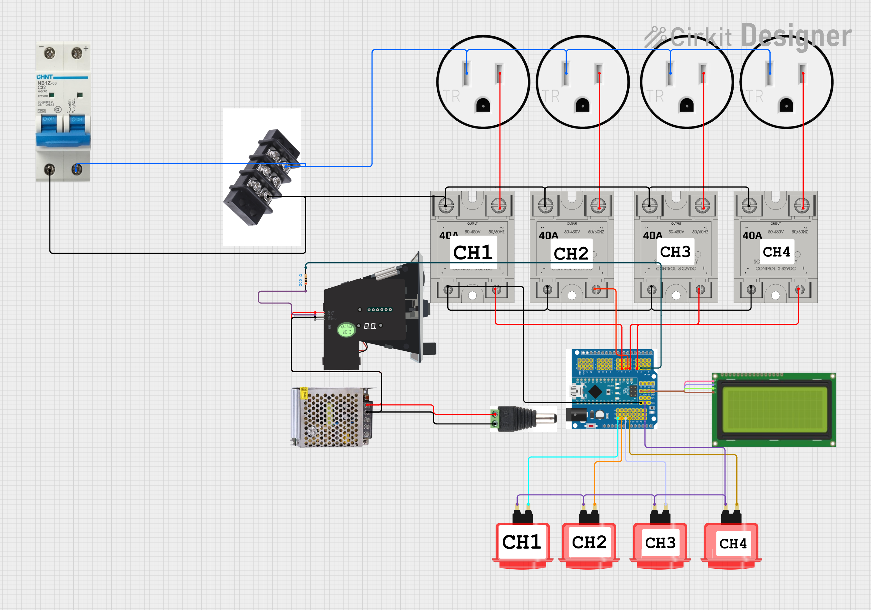
This circuit is designed to control a multi-stage process using an Arduino Expansion Board. The stages include Wash, Soap, Blow, and Water, each controlled by a Solid State Relay (SSR). The circuit also includes an LCD display for user interaction, arcade buttons for input, and a coin acceptor for payment. The system allows users to start and pause each stage, and it includes a settings mode for adjusting the countdown times and prices for each stage.
Component List
SSR-40A
- Description: Solid State Relay
- Pins: -, +, Lin, Lout
- Purpose: Controls the power to each stage (Wash, Soap, Blow, Water)
120V Outlet
- Description: Standard 120V AC outlet
- Pins: AC Neutral, AC Hot, GND
- Purpose: Provides AC power to external devices
Terminal Block
- Description: Terminal block for wire connections
- Pins: None
- Purpose: Provides a common connection point for multiple wires
Circuit Breaker
- Description: Circuit breaker for safety
- Pins: -, +
- Purpose: Protects the circuit from overcurrent
Arduino Expansion Board
- Description: Arduino-compatible microcontroller board
- Pins: 8, 9, 10, 11, 12, 13, GND, AREF, RX, TX, 2, 3, 4, 5, 6, 7, G, V, 1, 0, 5V, SCL, SDA, 3V3, A0, A1, A2, A3, A4, A5, A6, A7, RST, NC, VIN, POWER
- Purpose: Controls the entire system, including relays, buttons, and LCD
Lcd 20x4 i2c
- Description: 20x4 character LCD with I2C interface
- Pins: GND, 5v, SCA, SCL
- Purpose: Displays information to the user
Arcade Button (red)
- Description: Arcade-style push button
- Pins: no name yet
- Purpose: User input for starting and pausing stages
POWER SUPPLY 12V 5AMP
- Description: 12V DC power supply
- Pins: 220V Positive Pole (AC), 220V Negative Pole (AC), GND, GND (DC), 12V-24V Output (DC)
- Purpose: Provides 12V DC power to the circuit
2.1mm Male
- Description: 2.1mm male power connector
- Pins: +, -
- Purpose: Connects the power supply to the circuit
Multi Coin Acceptor
- Description: Coin acceptor for multiple coin types
- Pins: COIN, DC12V, GND, COUNTER
- Purpose: Accepts coins for payment
Resistor
- Description: 200 Ohm resistor
- Pins: pin1, pin2
- Purpose: Limits current in the circuit
Wiring Details
SSR-40A
- Pin +: Connected to Arduino Expansion Board pin 6
- Pin -: Connected to Arduino Expansion Board GND
- Pin Lin: Connected to Circuit Breaker pin -
- Pin Lout: Connected to 120V Outlet AC Hot
SSR-40A
- Pin +: Connected to Arduino Expansion Board pin 5
- Pin -: Connected to Arduino Expansion Board GND
- Pin Lin: Connected to Circuit Breaker pin -
- Pin Lout: Connected to 120V Outlet AC Hot
SSR-40A
- Pin +: Connected to Arduino Expansion Board pin 4
- Pin -: Connected to Arduino Expansion Board GND
- Pin Lin: Connected to Circuit Breaker pin -
- Pin Lout: Connected to 120V Outlet AC Hot
SSR-40A
- Pin +: Connected to Arduino Expansion Board pin 3
- Pin -: Connected to Arduino Expansion Board GND
- Pin Lin: Connected to Circuit Breaker pin -
- Pin Lout: Connected to 120V Outlet AC Hot
120V Outlet
- Pin AC Neutral: Connected to Circuit Breaker pin +
- Pin AC Hot: Connected to SSR-40A pin Lout
- Pin GND: Not connected
Terminal Block
- Pins: Connected to SSR-40A pin Lin and Circuit Breaker pin -
Circuit Breaker
- Pin -: Connected to SSR-40A pin Lin and Terminal Block
- Pin +: Connected to 120V Outlet AC Neutral
Arduino Expansion Board
- Pin 6: Connected to SSR-40A pin +
- Pin 5: Connected to SSR-40A pin +
- Pin 4: Connected to SSR-40A pin +
- Pin 3: Connected to SSR-40A pin +
- Pin 2: Connected to Resistor pin2
- Pin SCL: Connected to Lcd 20x4 i2c pin SCL
- Pin SDA: Connected to Lcd 20x4 i2c pin SCA
- Pin 5V: Connected to Lcd 20x4 i2c pin 5v
- Pin GND: Connected to Lcd 20x4 i2c pin GND, SSR-40A pin -, and Arcade Button pin no name yet
Lcd 20x4 i2c
- Pin SCL: Connected to Arduino Expansion Board pin SCL
- Pin SCA: Connected to Arduino Expansion Board pin SDA
- Pin 5v: Connected to Arduino Expansion Board pin 5V
- Pin GND: Connected to Arduino Expansion Board pin GND
Arcade Button (red)
- Pin no name yet: Connected to Arduino Expansion Board pin A0
- Pin no name yet: Connected to Arduino Expansion Board pin A1
- Pin no name yet: Connected to Arduino Expansion Board pin A2
- Pin no name yet: Connected to Arduino Expansion Board pin A3
- Pin no name yet: Connected to Arduino Expansion Board GND
POWER SUPPLY 12V 5AMP
- Pin 220V Positive Pole (AC): Not connected
- Pin 220V Negative Pole (AC): Not connected
- Pin GND: Not connected
- Pin GND (DC): Connected to 2.1mm Male pin -
- Pin 12V-24V Output (DC): Connected to 2.1mm Male pin +
2.1mm Male
- Pin -: Connected to POWER SUPPLY 12V 5AMP pin GND (DC)
- Pin +: Connected to POWER SUPPLY 12V 5AMP pin 12V-24V Output (DC)
Multi Coin Acceptor
- Pin COIN: Connected to Resistor pin1
- Pin DC12V: Connected to 2.1mm Male pin +
- Pin GND: Connected to 2.1mm Male pin -
Resistor
- Pin pin1: Connected to Multi Coin Acceptor pin COIN
- Pin pin2: Connected to Arduino Expansion Board pin 2
Documented Code
Arduino Expansion Board Code
#include <Wire.h>
#include <LiquidCrystal_I2C.h>
#include <EEPROM.h> // Include EEPROM library

// LCD setup
LiquidCrystal_I2C lcd(0x27, 20, 4);

// Button pins
const int buttonPins[4] = {A0, A1, A2, A3}; // A0: Cycle settings, A1: Toggle adjustment type, A2: Increase, A3: Decrease
// Relay pins
const int relayPins[4] = {7, 6, 5, 4};

// Coin acceptor pin
const int coinAcceptorPin = 2; // Pin connected to coin acceptor output

// Countdown time in seconds for each stage
int countdownTimes[4]; // Initialize without default values
// Prices for each stage
int prices[4]; // Initialize without default values

// Countdown timers
int timers[4] = {0, 0, 0, 0};
// Pause state for each timer
bool paused[4] = {true, true, true, true}; // Start with all timers paused

// Blink control
bool blinkState = false; // State for blinking
unsigned long previousMillis = 0; // Store the last time the text was updated
const long blinkInterval = 500; // Blink interval in milliseconds
unsigned long lastUpdateMillis = 0; // Store the last time the timers