
Arduino UNO-Based Real-Time Clock with I2C LCD Display and IO Expansion
View and Edit Project In Cirkit Designer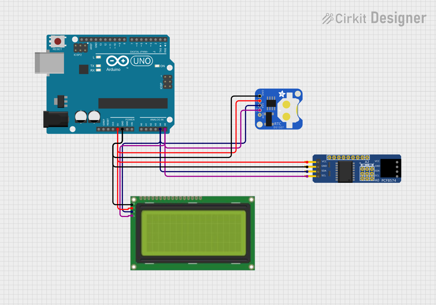
Circuit Documentation
Summary
This circuit integrates an Arduino UNO microcontroller with a DS1307 Real-Time Clock (RTC) module, a PCF8574 IO Expansion Board, and a 20x4 I2C LCD display. The purpose of this circuit is to display the current date and time on the LCD, which is fetched from the DS1307 RTC module. The PCF8574 IO Expansion Board is used to expand the I/O capabilities of the Arduino UNO.
Component List
Arduino UNO
- Description: A microcontroller board based on the ATmega328P.
- Pins: UNUSED, IOREF, Reset, 3.3V, 5V, GND, Vin, A0, A1, A2, A3, A4, A5, SCL, SDA, AREF, D13, D12, D11, D10, D9, D8, D7, D6, D5, D4, D3, D2, D1, D0
DS1307 RTC (Wokwi Compatible)
- Description: A real-time clock module that keeps track of the current time and date.
- Pins: GND, 5V, SDA, SCL, SQW
PCF8574 IO Expansion Board
- Description: An I2C-based I/O expander that provides additional GPIO pins.
- Pins: VCC, GND, SDA, SCL, A2+, A2c, A2-, A1+, A1c, A1-, A0+, A0c, A0-, O0, O1, O2, O3, O4, O5, O6, O7, INT
Lcd 20x4 i2c
- Description: A 20x4 character LCD display with I2C interface.
- Pins: GND, 5v, SCA, SCL
Wiring Details
Arduino UNO
- 5V: Connected to 5V of DS1307 RTC, VCC of PCF8574 IO Expansion Board, and 5v of Lcd 20x4 i2c
- GND: Connected to GND of DS1307 RTC, GND of PCF8574 IO Expansion Board, and GND of Lcd 20x4 i2c
- A4: Connected to SDA of DS1307 RTC, SDA of PCF8574 IO Expansion Board, and SCA of Lcd 20x4 i2c
- A5: Connected to SCL of DS1307 RTC, SCL of PCF8574 IO Expansion Board, and SCL of Lcd 20x4 i2c
DS1307 RTC (Wokwi Compatible)
- 5V: Connected to 5V of Arduino UNO, VCC of PCF8574 IO Expansion Board, and 5v of Lcd 20x4 i2c
- GND: Connected to GND of Arduino UNO, GND of PCF8574 IO Expansion Board, and GND of Lcd 20x4 i2c
- SDA: Connected to A4 of Arduino UNO, SDA of PCF8574 IO Expansion Board, and SCA of Lcd 20x4 i2c
- SCL: Connected to A5 of Arduino UNO, SCL of PCF8574 IO Expansion Board, and SCL of Lcd 20x4 i2c
PCF8574 IO Expansion Board
- VCC: Connected to 5V of Arduino UNO, 5V of DS1307 RTC, and 5v of Lcd 20x4 i2c
- GND: Connected to GND of Arduino UNO, GND of DS1307 RTC, and GND of Lcd 20x4 i2c
- SDA: Connected to A4 of Arduino UNO, SDA of DS1307 RTC, and SCA of Lcd 20x4 i2c
- SCL: Connected to A5 of Arduino UNO, SCL of DS1307 RTC, and SCL of Lcd 20x4 i2c
Lcd 20x4 i2c
- 5v: Connected to 5V of Arduino UNO, 5V of DS1307 RTC, and VCC of PCF8574 IO Expansion Board
- GND: Connected to GND of Arduino UNO, GND of DS1307 RTC, and GND of PCF8574 IO Expansion Board
- SCA: Connected to A4 of Arduino UNO, SDA of DS1307 RTC, and SDA of PCF8574 IO Expansion Board
- SCL: Connected to A5 of Arduino UNO, SCL of DS1307 RTC, and SCL of PCF8574 IO Expansion Board
Code Documentation
// Programa : Modulo I2C Display e Modulo DS1307
// Autor : Arduino e Cia

#include "Wire.h"
#include <LiquidCrystal_I2C.h>

// Modulo RTC no endereco 0x68
#define DS1307_ADDRESS 0x68

// Modulo I2C display no endereco 0x27
LiquidCrystal_I2C lcd(0x27,2,16);

byte zero = 0x00;

// Faça caracteres personalizados:
byte Square[] = {  B00000,  B11111,  B10001,  B10001,  B10001,  B10001,  B11111,  B00000};
byte Bell[] = { B00100, B01110, B01110, B01110, B11111, B00000, B00100, B00000 };
byte Right[] = { B00000, B01000, B01100, B01110, B01111, B01110, B01100, B01000 };
byte Check[] = { B00000, B00001, B00011, B10110, B11100, B01000, B00000, B00000 };
byte Speaker[] = { B00001, B00011, B01111, B01111, B01111, B00011, B00001, B00000 };
byte Sound[] = { B00001, B00011, B00101, B01001, B01001, B01011, B11011, B11000 };
byte Left[] = { B00000, B00010, B00110, B01110, B11110, B01110, B00110, B00010 };
byte Lock[] = { B01110, B10001, B10001, B11111, B11011, B11011, B11111, B00000 };

void setup()
{
  Wire.begin();
  Serial.begin(9600);
  lcd.begin (16,2);

  //A linha abaixo pode ser retirada apos setar a data e hora
  //SelecionaDataeHora();

  // Crie novos personagens:
  lcd.createChar(1, Square);
  lcd.createChar(2, Bell);
  lcd.createChar(3, Right);
  lcd.createChar(4, Check);
  lcd.createChar(5, Speaker);
  lcd.createChar(6, Sound);
  lcd.createChar(7, Left);
  lcd.createChar(8, Lock); //
}

void loop()
{
  // Le os valores (data e hora) do modulo DS1307
  Wire.beginTransmission(DS1307_ADDRESS);
  Wire.write(zero);
  Wire.endTransmission();
  Wire.requestFrom(DS1307_ADDRESS, 7);
  int segundos = ConverteparaDecimal(Wire.read());
  int minutos = ConverteparaDecimal(Wire.read());
  int horas = ConverteparaDecimal(Wire.read() & 0b111111);
  int diadasemana = ConverteparaDecimal(Wire.read());
  int diadomes = ConverteparaDecimal(Wire.read());
  int mes = ConverteparaDecimal(Wire.read());
  int ano = ConverteparaDecimal(Wire.read());

  // Mostra os dados no display
  lcd.setBacklight(HIGH); // liga backlight
  lcd.setCursor(8,1);
  //lcd.print("     ");
  // Acrescenta o 0 (zero) se a hora for menor do que 10
  if (horas <10)
    lcd.print("0");
  lcd.print(horas);
  lcd.print(":");
  // Acrescenta o 0 (zero) se minutos for menor do que 10
  if (minutos < 10)
     lcd.print("0");
  lcd.print(minutos);

lcd.print(":");
  // Acrescenta o 0 (zero) se segundos for menor do que 10
  if (segundos < 10)
     lcd.print("0");
  lcd.print(segundos);

  lcd.setCursor(2,0);
  // Mostra o dia da semana
  switch(diadasemana)
    {
      case 0:lcd.print("Dom");
      break;
      case 1:lcd.print("Seg");
      break;
      case 2:lcd