Cirkit Designer
Your all-in-one circuit design IDE
Home /
Project Documentation
Arduino UNO-Based Smart Environmental Monitoring System with Battery-Powered Water Pump Control
Circuit Documentation
Summary
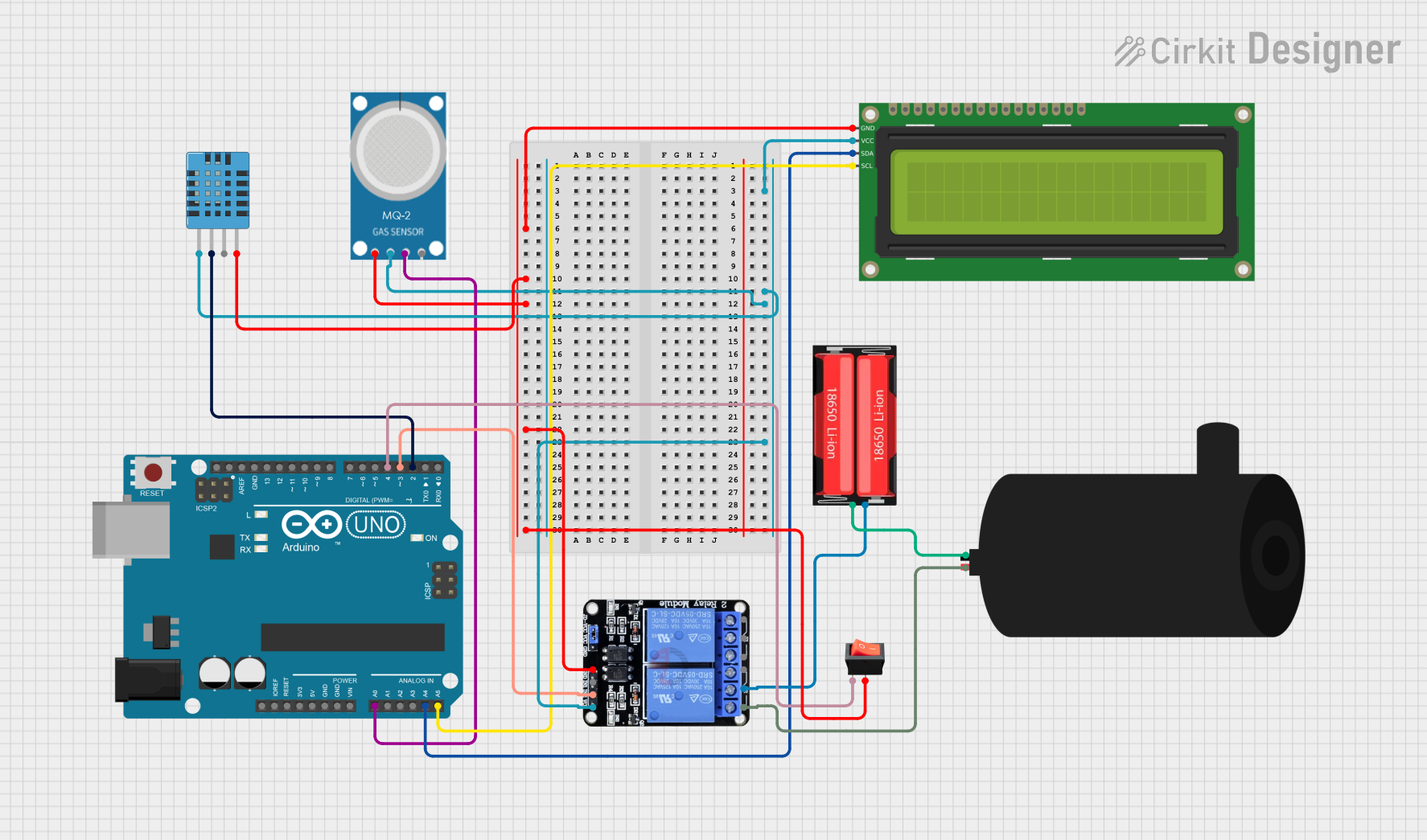
This circuit is designed to monitor environmental conditions such as humidity, temperature, and air quality. It also controls a water pump based on the state of a rocker switch. The main components include an Arduino UNO, a DHT11 humidity and temperature sensor, an MQ-2 gas sensor, a 16x2 I2C LCD, a two-channel relay, a water pump, a rocker switch, and a 18650 Li-Ion battery.
Component List
Arduino UNO
- Description: A microcontroller board based on the ATmega328P.
- Pins: UNUSED, IOREF, Reset, 3.3V, 5V, GND, Vin, A0, A1, A2, A3, A4, A5, SCL, SDA, AREF, D13, D12, D11, D10, D9, D8, D7, D6, D5, D4, D3, D2, D1, D0
DHT11 Humidity and Temperature Sensor
- Description: A sensor for measuring humidity and temperature.
- Pins: VDD, DATA, NULL, GND
MQ-2 Gas Sensor
- Description: A sensor for detecting gas levels.
- Pins: GND, VCC, ANALOG, Digital
Two Channel Relay 5V
- Description: A relay module for controlling high voltage devices.
- Pins: VCC, IN2, IN1, GND, NC2, C2, NO2, NC1, C1, NO1
18650 Li-Ion Battery
- Description: A rechargeable lithium-ion battery.
- Pins: Positive, Negative
Water Pump
- Description: A small water pump.
- Pins: positive, negative
Rocker Switch
- Description: A switch to control the water pump.
- Pins: output, input
16x2 I2C LCD
- Description: A 16x2 character LCD with I2C interface.
- Pins: GND, VCC, SDA, SCL
Wiring Details
Arduino UNO
- A0 connected to MQ-2 (ANALOG)
- A4 connected to 16x2 I2C LCD (SDA)
- A5 connected to 16x2 I2C LCD (SCL)
- D2 connected to DHT11 Humidity and Temperature Sensor (DATA)
- D3 connected to Two Channel Relay 5V (IN2)
- D4 connected to Rocker Switch (input)
DHT11 Humidity and Temperature Sensor
- VDD connected to 16x2 I2C LCD (VCC)
- DATA connected to Arduino UNO (D2)
- GND connected to 16x2 I2C LCD (GND)
MQ-2 Gas Sensor
- VCC connected to 16x2 I2C LCD (VCC)
- ANALOG connected to Arduino UNO (A0)
- GND connected to 16x2 I2C LCD (GND)
Two Channel Relay 5V
- VCC connected to 16x2 I2C LCD (VCC)
- IN2 connected to Arduino UNO (D3)
- GND connected to 16x2 I2C LCD (GND)
- NC2 connected to Water Pump (positive)
- C2 connected to 18650 Li-Ion Battery (Positive)
18650 Li-Ion Battery
- Positive connected to Two Channel Relay 5V (C2)
- Negative connected to Water Pump (negative)
Water Pump
- positive connected to Two Channel Relay 5V (NC2)
- negative connected to 18650 Li-Ion Battery (Negative)
Rocker Switch
- input connected to Arduino UNO (D4)
- output connected to 16x2 I2C LCD (GND)
16x2 I2C LCD
- VCC connected to DHT11 Humidity and Temperature Sensor (VDD)
- GND connected to DHT11 Humidity and Temperature Sensor (GND)
- SDA connected to Arduino UNO (A4)
- SCL connected to Arduino UNO (A5)
Code Documentation
#include <Wire.h>
#include <LiquidCrystal_I2C.h>
#include <DHT.h>

// Pin definitions
#define DHTPIN 2
#define DHTTYPE DHT11
#define MQ2PIN A0
#define RELAYPIN 3
#define SWITCHPIN 4

// Initialize the DHT sensor
DHT dht(DHTPIN, DHTTYPE);

// Initialize the LCD
LiquidCrystal_I2C lcd(0x27, 16, 2);

void setup() {
  // Start serial communication
  Serial.begin(9600);

  // Initialize the DHT sensor
  dht.begin();

  // Initialize the LCD
  lcd.init();
  lcd.backlight();

  // Set pin modes
  pinMode(MQ2PIN, INPUT);
  pinMode(RELAYPIN, OUTPUT);
  pinMode(SWITCHPIN, INPUT);

  // Initial state of the relay
  digitalWrite(RELAYPIN, LOW);
}

void loop() {
  // Read humidity and temperature from DHT11
  float humidity = dht.readHumidity();
  float temperature = dht.readTemperature();

  // Read air quality from MQ-2
  int airQuality = analogRead(MQ2PIN);

  // Display data on LCD
  lcd.clear();
  lcd.setCursor(0, 0);
  lcd.print("Hum: ");
  lcd.print(humidity);
  lcd.print("%");
  lcd.setCursor(0, 1);
  lcd.print("Temp: ");
  lcd.print(temperature);
  lcd.print("C AQ: ");
  lcd.print(airQuality);

  // Check the state of the switch
  if (digitalRead(SWITCHPIN) == HIGH) {
    // Turn on the water pump
    digitalWrite(RELAYPIN, HIGH);
  } else {
    // Turn off the water pump
    digitalWrite(RELAYPIN, LOW);
  }

  // Wait for a second before the next loop
  delay(1000);
}
This code initializes the sensors and LCD, reads data from the DHT11 and MQ-2 sensors, displays the data on the LCD, and controls the water pump based on the state of the rocker switch.