
Arduino UNO Based UV Intensity Monitoring System with LCD Display
View and Edit Project In Cirkit Designer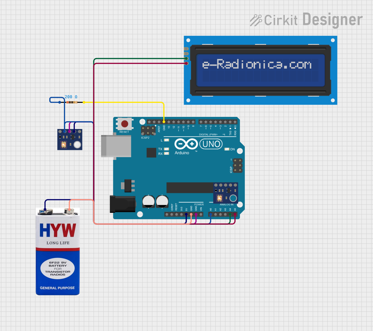
Circuit Documentation
Summary of the Circuit
This circuit is designed to measure UV intensity using an ML8511 UV sensor and display the results on an LCD screen. The system is powered by a 9V battery and utilizes two Arduino UNO microcontrollers, although only one is actively used in the current configuration. The active Arduino reads the UV sensor data, processes it, and then displays the UV intensity on the LCD screen. The LCD screen is interfaced with the Arduino using I2C communication.
Component List
Arduino UNO
- Microcontroller board based on the ATmega328P
- It has 14 digital input/output pins, 6 analog inputs, a 16 MHz quartz crystal, a USB connection, a power jack, an ICSP header, and a reset button.
ML8511 Breakout Board
- UV light sensor that can detect the UV-A and UV-B spectrum.
- It outputs an analog signal proportional to the amount of UV light detected.
Resistor
- A passive two-terminal electrical component that implements electrical resistance as a circuit element.
- In this circuit, a 200 Ohm resistor is used.
LCD screen 16x2 I2C
- An alphanumeric LCD display module that can show 16 characters in 2 rows.
- It has an I2C interface for communication which reduces the pin usage on the Arduino.
9V battery
- A standard 9V battery used to power the circuit.
Wiring Details
Arduino UNO
- 5V connected to the positive terminal of the 9V battery.
- GND connected to the negative terminal of the 9V battery.
- A0 connected to the ML8511 UV sensor's output through a 200 Ohm resistor.
- A4 (SDA) connected to the SDA pin of the LCD screen.
- A5 (SCL) connected to the SCL pin of the LCD screen.
ML8511 Breakout Board
- 3V3 connected to the 5V output from the Arduino UNO.
- GND connected to the ground (GND) on the Arduino UNO.
- OUT connected to the A0 pin on the Arduino UNO through a 200 Ohm resistor.
Resistor
- One pin connected to the A0 pin on the Arduino UNO.
- The other pin connected to the OUT pin of the ML8511 UV sensor.
LCD screen 16x2 I2C
- SDA connected to the A4 pin on the Arduino UNO.
- SCL connected to the A5 pin on the Arduino UNO.
- VCC and GND not explicitly connected in the provided net list, but typically these would be connected to 5V and GND on the Arduino UNO, respectively.
9V battery
- + connected to the 5V pin on the Arduino UNO.
- - connected to the GND pin on the Arduino UNO.
Documented Code
Arduino UNO Code for UV Intensity Measurement and Display
#include <Wire.h>
#include <LiquidCrystal_I2C.h>  // For the LCD I2C

LiquidCrystal_I2C lcd(0x27, 16, 2);  // I2C address for the LCD

int uvSensorPin = A0; // Analog pin for the ML8511 UV sensor
float uvIntensity;

void setup() {
  lcd.begin();  // Initialize the LCD
  lcd.backlight();  // Turn on the back light of LCD
  lcd.setCursor(0, 0);
  lcd.print("UV Intensity:");

  Serial.begin(9600); // Start serial communication for debugging
}

void loop() {
  int uvLevel = analogRead(uvSensorPin);  // Read data from the UV sensor
  float voltage = uvLevel * (5.0 / 1023.0);  // Convert to voltage

  // Calibrate the sensor to UV radiation values
  uvIntensity = map(uvLevel, 0, 1023, 0, 15); // Scale to a simple UV index

  lcd.setCursor(0, 1);  // Second line on the LCD
  lcd.print(uvIntensity);  // Display the UV value

  Serial.print("UV Level: ");
  Serial.println(uvIntensity);  // Debug in serial monitor

  delay(1000);  // Wait for 1 second before the next reading
}
Arduino UNO Placeholder Code (Unused in Current Configuration)
void setup() {
  // put your setup code here, to run once:

}

void loop() {
  // put your main code here, to run repeatedly:

}
This concludes the documentation for the UV intensity measurement circuit. The circuit is designed for educational purposes and provides a practical application of interfacing sensors and displays with a microcontroller.