
ESP32-CAM and Arduino UNO Based Face Recognition Door Lock System with 12V Solenoid Lock
View and Edit Project In Cirkit Designer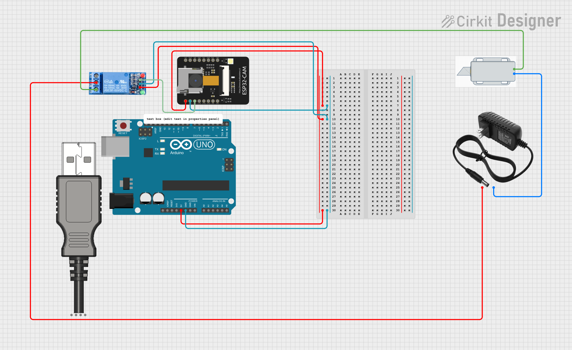
Circuit Documentation
Summary
This circuit is a door lock system using face recognition. It consists of an ESP32-CAM module for face recognition, an Arduino UNO, a 12V solenoid lock, a 1-channel relay module, and a 12V power supply. When a recognized face is detected by the ESP32-CAM, the relay activates the solenoid lock to unlock the door.
Component List
12V Solenoid Lock
- Description: Electromechanical lock that operates on 12V.
- Pins:
-,+
ESP32-CAM
- Description: Microcontroller with camera module for face recognition.
- Pins:
5V,GND,IO12,IO13,IO15,IO14,IO2,IO4,VOT,VOR,VCC,IO0,IO16,3V3
Arduino UNO
- Description: Microcontroller board based on the ATmega328P.
- Pins:
UNUSED,IOREF,Reset,3.3V,5V,GND,Vin,A0,A1,A2,A3,A4,A5,SCL,SDA,AREF,D13,D12,D11,D10,D9,D8,D7,D6,D5,D4,D3,D2,D1,D0
USB Plug
- Description: Standard USB plug for power and data.
- Pins:
GND,D+,D-,5V+,Out
1 Channel Relay 5V
- Description: Relay module that operates on 5V.
- Pins:
VCC,GND,IN,NC,COM,NO
12V Power Supply
- Description: Power supply providing 12V output.
- Pins:
+,-
Comment
- Description: Placeholder for comments or notes.
- Pins: None
Wiring Details
12V Solenoid Lock
- Pin
-is connected to 12V Power Supply-. - Pin
+is connected to 1 Channel Relay 5VNO.
ESP32-CAM
- Pin
5Vis connected to 1 Channel Relay 5VVCCand Arduino UNO5V. - Pin
GNDis connected to 1 Channel Relay 5VGNDand Arduino UNOGND. - Pin
IO12is connected to 1 Channel Relay 5VIN.
Arduino UNO
- Pin
5Vis connected to ESP32-CAM5Vand 1 Channel Relay 5VVCC. - Pin
GNDis connected to ESP32-CAMGNDand 1 Channel Relay 5VGND.
USB Plug
- Not connected in this circuit.
1 Channel Relay 5V
- Pin
VCCis connected to ESP32-CAM5Vand Arduino UNO5V. - Pin
GNDis connected to ESP32-CAMGNDand Arduino UNOGND. - Pin
INis connected to ESP32-CAMIO12. - Pin
NOis connected to 12V Solenoid Lock+. - Pin
COMis connected to 12V Power Supply+.
12V Power Supply
- Pin
+is connected to 1 Channel Relay 5VCOM. - Pin
-is connected to 12V Solenoid Lock-.
Documented Code
Arduino UNO Code
/*
 * This Arduino Sketch is part of a door lock system using face recognition.
 * The microcontroller with instance ID fc6e7b11-07d8-4752-9288-9e7c96f60b35
 * is connected to a 12V Solenoid Lock and a 1-Channel Relay module. The relay
 * is controlled by an ESP32-CAM module, which performs face recognition. When
 * a recognized face is detected, the relay activates the solenoid lock to
 * unlock the door.
 */

const int relayPin = 4; // Relay signal pin connected to ESP32-CAM IO4

void setup() {
  pinMode(relayPin, OUTPUT); // Set relay pin as output
  digitalWrite(relayPin, LOW); // Ensure relay is off initially
}

void loop() {
  // Placeholder for face recognition logic
  // This should be replaced with actual communication from ESP32-CAM
  bool faceRecognized = true; // Simulated face recognition result

  if (faceRecognized) {
    digitalWrite(relayPin, HIGH); // Activate relay to unlock door
    delay(5000); // Keep the door unlocked for 5 seconds
    digitalWrite(relayPin, LOW); // Deactivate relay to lock door
  }

  delay(100); // Short delay to avoid rapid toggling
}
ESP32-CAM Code
#include <WiFi.h>

// Configuration du relais
#define RELAY_PIN 12

void setup() {
  pinMode(RELAY_PIN, OUTPUT);
  digitalWrite(RELAY_PIN, LOW); // Assurez-vous que le relais est désactivé au démarrage

  // Configuration Wi-Fi ou reconnaissance faciale (ajoutez vos propres paramètres ici)
  Serial.begin(115200);
  Serial.println("ESP32-CAM ready!");
}

void loop() {
  // Simule la reconnaissance faciale (remplacez par votre code)
  bool faceRecognized = true; // Exemple : Remplacez par une condition réelle

  if (faceRecognized) {
    digitalWrite(RELAY_PIN, HIGH); // Active le relais
    Serial.println("Face recognized! Door unlocked.");
    delay(5000); // Maintient la serrure ouverte pendant 5 secondes
    digitalWrite(RELAY_PIN, LOW);  // Désactive le relais
    Serial.println("Door locked.");
  }

  delay(1000); // Pause pour éviter des boucles rapides
}
Additional Arduino UNO Code
void setup() {
  // put your setup code here, to run once:

}

void loop() {
  // put your main code here, to run repeatedly:

}
This documentation provides a comprehensive overview of the circuit, including a summary, detailed component list, wiring details, and documented code for the microcontrollers involved.