
Circuit Documentation
Summary of the Circuit
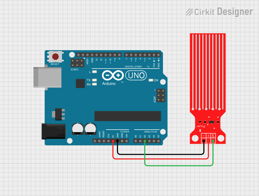
This circuit consists of an Arduino UNO microcontroller board interfaced with a Water Level Sensor. The Arduino UNO is responsible for providing power to the sensor and reading its signal to determine the water level. The sensor's signal pin is connected to one of the analog input pins on the Arduino, allowing the microcontroller to measure the analog voltage corresponding to the water level.
Component List
Arduino UNO
- Description: A microcontroller board based on the ATmega328P.
- Pins: UNUSED, IOREF, Reset, 3.3V, 5V, GND, Vin, A0-A5, SCL, SDA, AREF, D0-D13.
- Purpose: Acts as the central processing unit of the circuit, reading sensor data and executing embedded code.
Water Level Sensor
- Description: A sensor that measures the level of water through electrical conductivity.
- Pins: SIG, VCC, GND.
- Purpose: Provides an analog voltage output that varies with the water level.
Wiring Details
Arduino UNO
- 5V: Provides power to the Water Level Sensor.
- GND: Common ground with the Water Level Sensor.
- A2: Reads the analog signal from the Water Level Sensor.
Water Level Sensor
- VCC: Connected to the 5V output from the Arduino UNO.
- GND: Connected to the ground (GND) on the Arduino UNO.
- SIG: Outputs an analog signal to the A2 pin on the Arduino UNO.
Documented Code
Arduino UNO Code (sketch.ino)
void setup() {
  // put your setup code here, to run once:

}

void loop() {
  // put your main code here, to run repeatedly:

}
Note: The provided code is a template and does not contain any functional code to interact with the Water Level Sensor. To complete the circuit functionality, code must be added to initialize the A2 pin as an input and to read the analog value from the sensor in the loop function.