Arduino-Based Automatic Drainage Water Monitoring & Flood Control System with Air Quality and Pressure Sensors
Circuit Documentation
Summary
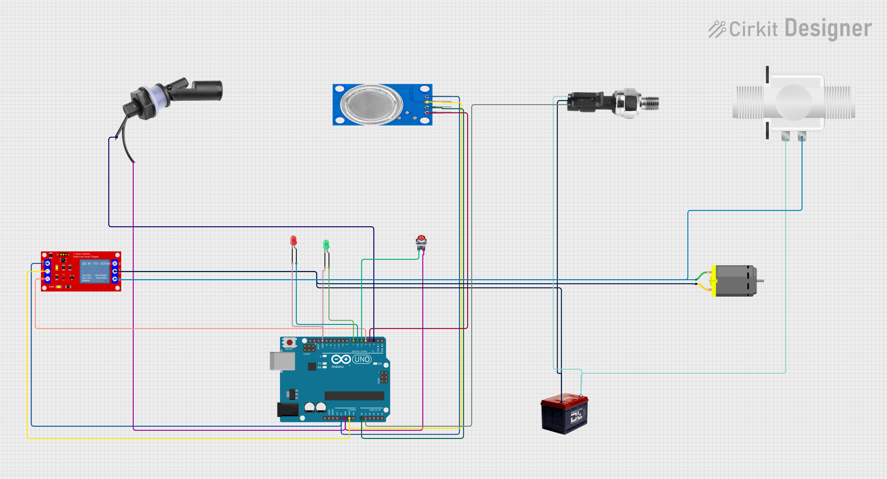
This document describes an Arduino-based automatic drainage water monitoring and flood control system. The system monitors water levels, air quality, and pressure to control a drainage system. It uses a float switch, MQ135 air quality sensor, pressure sensor, relay module, DC motor, solenoid valve, and LEDs for status indication. The system stops the motor and closes the valve when the stop button is pressed.
Component List
Arduino UNO
- Description: Microcontroller board based on the ATmega328P.
- Pins: UNUSED, IOREF, Reset, 3.3V, 5V, GND, Vin, A0, A1, A2, A3, A4, A5, SCL, SDA, AREF, D13, D12, D11, D10, D9, D8, D7, D6, D5, D4, D3, D2, D1, D0
Water Level Float Switch Sensor
- Description: Sensor to detect water level.
- Pins: Wire2, Wire1
MQ135
- Description: Air quality sensor.
- Pins: VCC, GND, A0, D0
Industrial Pressure Sensor
- Description: Sensor to measure pressure.
- Pins: DC+, DC-, Signal
DC Motor
- Description: Motor for drainage system.
- Pins: pin 1, pin 2
Plastic Solenoid Valve
- Description: Valve to control water flow.
- Pins: pin1, pin2
1 Channel 5V Relay Module
- Description: Relay module to control high power devices.
- Pins: VCC+, VCC- (GND), IN, N.O., COM, N.C.
LED: Two Pin (red)
- Description: Red LED for status indication.
- Pins: cathode, anode
LED: Two Pin (green)
- Description: Green LED for status indication.
- Pins: cathode, anode
Pushbutton STOP
- Description: Button to stop the system.
- Pins: NC, NO
Battery 12v
- Description: Power source.
- Pins: -, +
Wiring Details
Arduino UNO
- 5V connected to VCC+ of 1 Channel 5V Relay Module and VCC of MQ135.
- GND connected to Wire2 of Water Level Float Switch Sensor, NO of Pushbutton STOP, VCC- (GND) of 1 Channel 5V Relay Module, GND of MQ135, cathode of LED (green), and cathode of LED (red).
- A0 connected to A0 of MQ135.
- A1 connected to Signal of Industrial Pressure Sensor.
- D7 connected to anode of LED (green).
- D6 connected to anode of LED (red).
- D5 connected to NO of Pushbutton STOP.
- D4 connected to IN of 1 Channel 5V Relay Module.
- D3 connected to D0 of MQ135.
- D2 connected to Wire1 of Water Level Float Switch Sensor.
Water Level Float Switch Sensor
- Wire2 connected to GND of Arduino UNO.
- Wire1 connected to D2 of Arduino UNO.
MQ135
- VCC connected to 5V of Arduino UNO.
- GND connected to GND of Arduino UNO.
- A0 connected to A0 of Arduino UNO.
- D0 connected to D3 of Arduino UNO.
Industrial Pressure Sensor
- Signal connected to A1 of Arduino UNO.
- DC+ connected to + of Battery 12v and pin1 of Plastic Solenoid Valve.
- DC- connected to pin 2 of DC Motor.
DC Motor
- pin 1 connected to N.O. of 1 Channel 5V Relay Module.
- pin 2 connected to DC- of Industrial Pressure Sensor.
Plastic Solenoid Valve
- pin1 connected to DC+ of Industrial Pressure Sensor.
- pin2 connected to N.O. of 1 Channel 5V Relay Module.
1 Channel 5V Relay Module
- VCC+ connected to 5V of Arduino UNO.
- VCC- (GND) connected to GND of Arduino UNO.
- IN connected to D4 of Arduino UNO.
- N.O. connected to pin 1 of DC Motor and pin2 of Plastic Solenoid Valve.
- COM connected to - of Battery 12v.
LED: Two Pin (red)
- cathode connected to GND of Arduino UNO.
- anode connected to D6 of Arduino UNO.
LED: Two Pin (green)
- cathode connected to GND of Arduino UNO.
- anode connected to D7 of Arduino UNO.
Pushbutton STOP
- NO connected to GND of Arduino UNO and D5 of Arduino UNO.
Battery 12v
- + connected to DC+ of Industrial Pressure Sensor.
- - connected to COM of 1 Channel 5V Relay Module.
Code Documentation
/*
 * Arduino-Based Automatic Drainage Water Monitoring & Flood Control System
 *
 * This system monitors water levels, air quality, and pressure to control a
 * drainage system. It uses a float switch, MQ135 air quality sensor, pressure
 * sensor, relay module, DC motor, solenoid valve, and LEDs for status
 * indication. The system stops the motor and closes the valve when the stop
 * button is pressed.
 */

// Pin definitions
const int floatSwitchPin = 2;
const int stopButtonPin = 5;
const int relayPin = 4;
const int redLEDPin = 6;
const int greenLEDPin = 7;
const int mq135AnalogPin = A0;
const int pressureSensorPin = A1;

void setup() {
  // Initialize serial communication
  Serial.begin(9600);

  // Initialize pins
  pinMode(floatSwitchPin, INPUT);
  pinMode(stopButtonPin, INPUT);
  pinMode(relayPin, OUTPUT);
  pinMode(redLEDPin, OUTPUT);
  pinMode(greenLEDPin, OUTPUT);

  // Initial state
  digitalWrite(relayPin, LOW); // Relay off
  digitalWrite(redLEDPin, LOW); // Red LED off
  digitalWrite(greenLEDPin, LOW); // Green LED off
}

void loop() {
  // Read sensor values
  int floatSwitchState = digitalRead(floatSwitchPin);
  int stopButtonState = digitalRead(stopButtonPin);
  int mq135Value = analogRead(mq135AnalogPin);
  int pressureValue = analogRead(pressureSensorPin);

  // Print sensor values to serial monitor
  Serial.print("Float Switch: ");
  Serial.println(floatSwitchState);
  Serial.print("Stop Button: ");
  Serial.println(stopButtonState);
  Serial.print("MQ135 Value: ");
  Serial.println(mq135Value);
  Serial.print("Pressure Value: ");
  Serial.println(pressureValue);

  // Control logic
  if (stopButtonState == HIGH) {
    // Stop button pressed
    digitalWrite(relayPin, LOW); // Turn off relay
    digitalWrite(redLEDPin, HIGH); // Turn on red LED
    digitalWrite(greenLEDPin, LOW); // Turn off green LED
  } else if (floatSwitchState == HIGH) {
    // Float switch activated
    digitalWrite(relayPin, HIGH); // Turn on relay
    digitalWrite(redLEDPin, LOW); // Turn off red LED
    digitalWrite(greenLEDPin, HIGH); // Turn on green LED
  } else {
    // Default state
    digitalWrite(relayPin, LOW); // Turn off relay
    digitalWrite(redLEDPin, LOW); // Turn off red LED
    digitalWrite(greenLEDPin, LOW); // Turn off green LED
  }

  // Delay for stability
  delay(500);
}
This code initializes the pins and sets up the initial state of the system. In the loop function, it reads the sensor values and controls the relay and LEDs based on the state of the float switch and stop button. The sensor values are also printed to the serial monitor for debugging purposes.