
ESP32-Based Smart Irrigation System with Wi-Fi Connectivity and Dual Water Level Monitoring
View and Edit Project In Cirkit Designer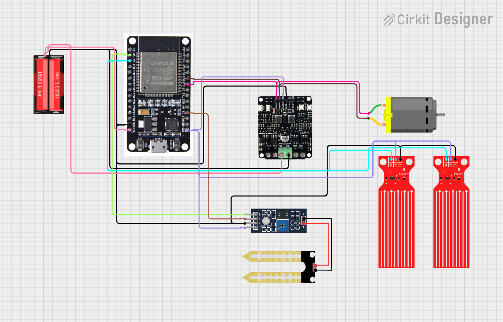
Circuit Documentation
Summary
The circuit in question is designed to monitor environmental conditions such as humidity and water level, and to control a DC motor based on these readings. The core of the circuit is an ESP32 microcontroller, which is responsible for reading sensor data, controlling the motor driver, and communicating with a server over WiFi. The circuit includes a humidity sensor (YL-69), two water level sensors, a 18650 Li-Ion battery for power, a motor driver to control the DC motor, and the DC motor itself.
Component List
Humidity Sensor (YL-69)
- Description: A sensor used to measure the humidity of the soil.
- Pins: A0 (Analog Output), D0 (Digital Output), GND (Ground), VCC (Power Supply).
18650 Li-Ion Battery
- Description: A rechargeable battery providing power to the circuit.
- Pins: Positive, Negative.
ESP32 Microcontroller
- Description: A powerful microcontroller with WiFi capabilities.
- Pins: EN, VP, VN, D34, D35, D32, D33, D25, D26, D27, D14, D12, D13, GND, VIN, 3V3, D15, D2, D4, RX2, TX2, D5, D18, D19, D21, RX0, TX0, D22, D23, BOOT.
Motor Driver
- Description: A module to control the DC motor.
- Pins: VB+ (Motor Power Supply Positive), VB- (Motor Power Supply Negative), M1A, M1B (Motor Control Pins), M2A, M2B (Unused Motor Control Pins), 5V (5V Output), GND (Ground).
DC Motor
- Description: A motor that converts electrical energy into mechanical motion.
- Pins: pin 1, pin 2.
Water Level Sensor
- Description: A sensor used to detect the level of water.
- Pins: SIG (Signal), VCC (Power Supply), GND (Ground).
Wiring Details
Humidity Sensor (YL-69)
- A0 connected to ESP32 VP
- D0 connected to ESP32 D2
- GND connected to common ground
- VCC connected to common 3V3
18650 Li-Ion Battery
- Positive connected to Motor Driver VB+ and ESP32 VIN
- Negative connected to common ground
ESP32 Microcontroller
- VP connected to Humidity Sensor A0
- VN connected to Water Level Sensor SIG
- D2 connected to Humidity Sensor D0
- D18 connected to Motor Driver M1A
- D19 connected to Motor Driver M1B
- GND connected to common ground
- VIN connected to 18650 Li-Ion Positive
- 3V3 connected to common 3V3
Motor Driver
- VB+ connected to 18650 Li-Ion Positive
- VB- connected to common ground
- M1A connected to ESP32 D18 and DC Motor pin 1
- M1B connected to ESP32 D19 and DC Motor pin 2
- 5V connected to common 3V3
- GND connected to common ground
DC Motor
- pin 1 connected to Motor Driver M1A
- pin 2 connected to Motor Driver M1B
Water Level Sensor
- SIG connected to ESP32 VN
- VCC connected to common 3V3
- GND connected to common ground
Documented Code
ESP32 Microcontroller Code
#include <WiFi.h>
#include <HTTPClient.h>
#include <L298N.h>

// Pin Definitions
const int humidityAnalogPin = VP; // A0 pin of Humidity YL-69
const int humidityDigitalPin = D2; // D0 pin of Humidity YL-69
const int waterLevelPin = VN; // SIG pin of Water Level Sensor

// Motor Pins
const int motorPin1 = D18; // IN1 pin of L298N
const int motorPin2 = D19; // IN2 pin of L298N
const int enablePin = D5;  // ENA pin of L298N

// WiFi Credentials
const char* ssid = "your_SSID";
const char* password = "your_PASSWORD";

// Create L298N instance
L298N motor(motorPin1, motorPin2, enablePin);

void setup() {
  // Initialize Serial Monitor
  Serial.begin(115200);

  // Initialize Pins
  pinMode(humidityAnalogPin, INPUT);
  pinMode(humidityDigitalPin, INPUT);
  pinMode(waterLevelPin, INPUT);

  // Initialize Motor
  motor.setSpeed(0); // Set initial speed to 0

  // Connect to WiFi
  WiFi.begin(ssid, password);
  while (WiFi.status() != WL_CONNECTED) {
    delay(1000);
    Serial.println("Connecting to WiFi...");
  }
  Serial.println("Connected to WiFi");
}

void loop() {
  // Read Humidity Sensor
  int humidityValue = analogRead(humidityAnalogPin);
  int humidityDigitalValue = digitalRead(humidityDigitalPin);
  Serial.print("Humidity Analog Value: ");
  Serial.println(humidityValue);
  Serial.print("Humidity Digital Value: ");
  Serial.println(humidityDigitalValue);

  // Read Water Level Sensor
  int waterLevelValue = analogRead(waterLevelPin);
  Serial.print("Water Level Value: ");
  Serial.println(waterLevelValue);

  // Control Motor Based on Sensor Readings
  if (humidityDigitalValue == LOW || waterLevelValue < 500) {
    // Turn on Motor
    motor.setSpeed(255); // Set speed to maximum
    motor.forward();     // Move motor forward
  } else {
    // Turn off Motor
    motor.setSpeed(0);   // Stop motor
  }

  // Send Data to Server
  if (WiFi.status() == WL_CONNECTED) {
    HTTPClient http;
    http.begin("http://yourserver.com/api/data");
    http.addHeader("Content-Type", "application/json");

    String jsonData = "{\"humidityAnalog\":" + String(humidityValue) +
                      ",\"humidityDigital\":" + String(humidityDigitalValue) +
                      ",\"waterLevel\":" + String(waterLevelValue) + "}";

    int httpResponseCode = http.POST(jsonData);
    if (httpResponseCode > 0) {
      String response = http.getString();
      Serial.println(httpResponseCode);
      Serial.println(response);
    } else {
      Serial.print("Error on sending POST: ");
      Serial.println(httpResponseCode);
    }
    http.end();
  }

  // Delay for Stability
  delay(1000);
}
This code is responsible for initializing the ESP32 microcontroller and its connected components, reading sensor data, controlling the motor based on the sensor data, and sending the sensor data to a server over WiFi.