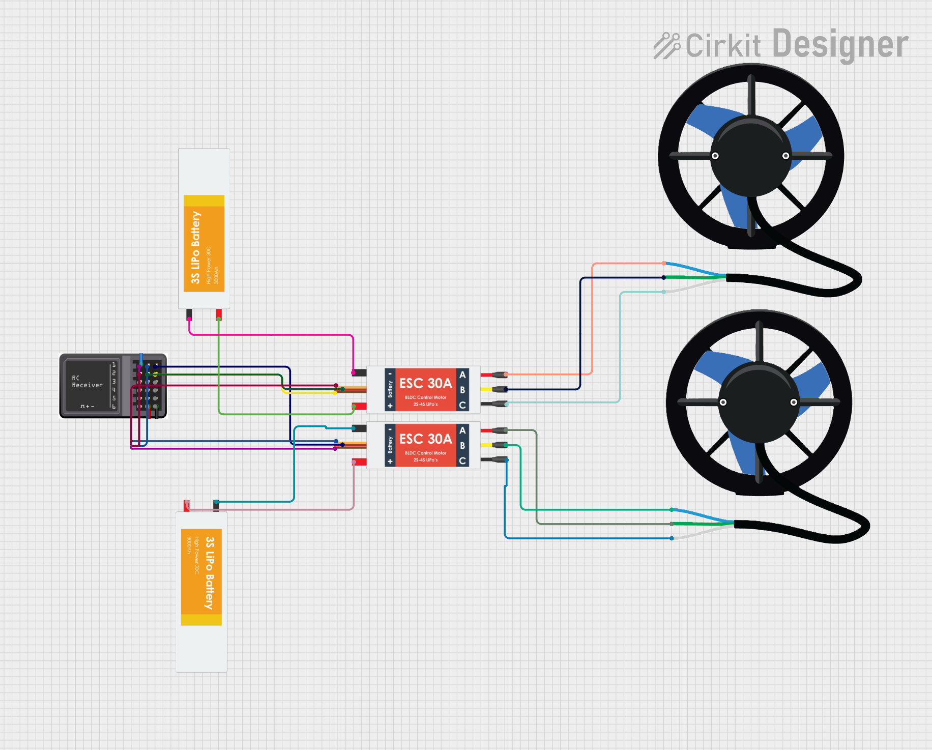
RC Receiver Controlled Dual T200 Thruster System

Circuit Documentation
Summary of the Circuit
This circuit is designed to control two T200 Thrusters using signals from an RC Receiver Module. The thrusters are powered by individual Lipo Batteries and are managed by Electronic Speed Controllers (ESCs). The ESCs receive control signals from the RC Receiver Module to regulate the speed and direction of the thrusters. The ESCs also provide power to the RC Receiver Module. There is no microcontroller code provided, indicating that the RC Receiver Module directly controls the ESCs without the need for additional processing.
Component List
RC Receiver Module
- Description: A radio control receiver module that receives signals from a remote transmitter.
- Pins: S6, S5, S4, S3, S2, S1, Vcc, GND
T200 Thruster (x2)
- Description: A high-performance underwater thruster designed for various aquatic applications.
- Pins: A, B, C
Electronic Speed Controller (ESC) (x2)
- Description: An electronic circuit that controls and regulates the speed of an electric motor.
- Pins: Battery VCC, Battery GND, Signal, 5v out, GND out, M1, M2, M3
Lipo Battery (x2)
- Description: A rechargeable battery of lithium-ion technology used for powering the circuit.
- Pins: VCC, GND
Wiring Details
RC Receiver Module
- Vcc: Connected to the 5v out pin of an ESC.
- GND: Connected to the GND out pin of an ESC.
- S1: Connected to the GND out pin of an ESC (possibly for signal reference).
- S2: Connected to the Signal pin of an ESC (control signal).
T200 Thruster
- A: Connected to the M1 pin of an ESC.
- B: Connected to the M2 pin of an ESC.
- C: Connected to the M3 pin of an ESC.
Electronic Speed Controller (ESC)
- Battery VCC: Connected to the VCC pin of a Lipo Battery.
- Battery GND: Connected to the GND pin of a Lipo Battery.
- Signal: Connected to the S2 pin of the RC Receiver Module.
- 5v out: Provides power to the Vcc pin of the RC Receiver Module.
- GND out: Connected to the GND pin of the RC Receiver Module and possibly to the S1 pin for signal reference.
- M1, M2, M3: Connected to the corresponding A, B, C pins of a T200 Thruster.
Lipo Battery
- VCC: Provides power to the Battery VCC pin of an ESC.
- GND: Connected to the Battery GND pin of an ESC.
Documented Code
No code has been provided for any microcontrollers in this circuit. The RC Receiver Module appears to be used in a standalone configuration, directly interfacing with the ESCs without the need for additional programming.