Cirkit Designer
Your all-in-one circuit design IDE
Home /
Project Documentation
Arduino Mega 2560 Controlled LED Matrix and Ultrasonic Sensor Display

Circuit Documentation
Summary
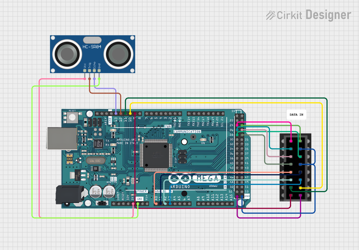
This circuit integrates an Arduino Mega 2560 microcontroller with an HC-SR04 Ultrasonic Sensor and a 64x32 LED Matrix display. The Arduino Mega 2560 serves as the central processing unit, controlling the LED Matrix for visual output and interfacing with the HC-SR04 Ultrasonic Sensor for distance measurement. The circuit is designed to provide a visual representation of sensor readings and can be expanded for various applications such as distance monitoring systems.
Component List
Arduino Mega 2560
- Description: A microcontroller board based on the ATmega2560.
- Purpose: Acts as the central controller for the circuit, interfacing with the LED Matrix and the Ultrasonic Sensor.
- Pins: IOREF, RESET, 3V3, 5V, GND, VIN, Analog Pins (A0-A15), Digital Pins (D0-D53), PWM Pins, Communication Pins (TX, RX, SCL, SDA), AREF, and additional power pins.
LED Matrix 64x32
- Description: A 64x32 pixel LED display matrix for visual output.
- Purpose: Displays visual information as directed by the Arduino Mega 2560.
- Pins: R1, B1, R2, B2, A, C, CLK, OE, G1, GND, G2, B, D, LAT.
HC-SR04 Ultrasonic Sensor
- Description: An ultrasonic distance sensor capable of measuring distances by emitting ultrasonic waves.
- Purpose: Measures distances and provides feedback to the Arduino Mega 2560.
- Pins: VCC, TRIG, ECHO, GND.
Wiring Details
Arduino Mega 2560
- 5V to HC-SR04 Ultrasonic Sensor VCC
- GND to HC-SR04 Ultrasonic Sensor GND and LED Matrix GND
- A0 to LED Matrix A
- A1 to LED Matrix B
- A2 to LED Matrix C
- A3 to LED Matrix D
- D9 PWM to LED Matrix OE
- D10 PWM to LED Matrix LAT
- D11 PWM to LED Matrix CLK
- D12 PWM to HC-SR04 Ultrasonic Sensor TRIG
- D13 PWM to HC-SR04 Ultrasonic Sensor ECHO
- D28 to LED Matrix G2
- D26 to LED Matrix B1
- D24 to LED Matrix R1
- D29 to LED Matrix B2
- D27 to LED Matrix R2
- D25 to LED Matrix G1
LED Matrix 64x32
- R1, B1, R2, B2, A, C, CLK, OE, G1, G2, B, D, LAT connected to corresponding pins on the Arduino Mega 2560.
- Multiple GND pins connected to Arduino Mega 2560 GND.
HC-SR04 Ultrasonic Sensor
- VCC to Arduino Mega 2560 5V
- GND to Arduino Mega 2560 GND
- TRIG to Arduino Mega 2560 D12 PWM
- ECHO to Arduino Mega 2560 D13 PWM
Documented Code
Arduino Mega 2560 Code (sketch.ino)
void setup() {
  // put your setup code here, to run once:

}

void loop() {
  // put your main code here, to run repeatedly:

}
Additional Notes
- The provided code is a template and does not contain any functional implementation. It needs to be populated with the logic for controlling the LED Matrix and reading data from the HC-SR04 Ultrasonic Sensor.
- The
setup()function is intended for initialization code that runs once at the start, such as pin mode configurations. - The
loop()function is for code that runs continuously, which will include the main logic for sensor data acquisition and display updates.