Cirkit Designer
Your all-in-one circuit design IDE
Home /
Project Documentation
Arduino UNO-Based Water Management System with Ultrasonic Sensors and Solenoid Valves

Circuit Documentation
Summary
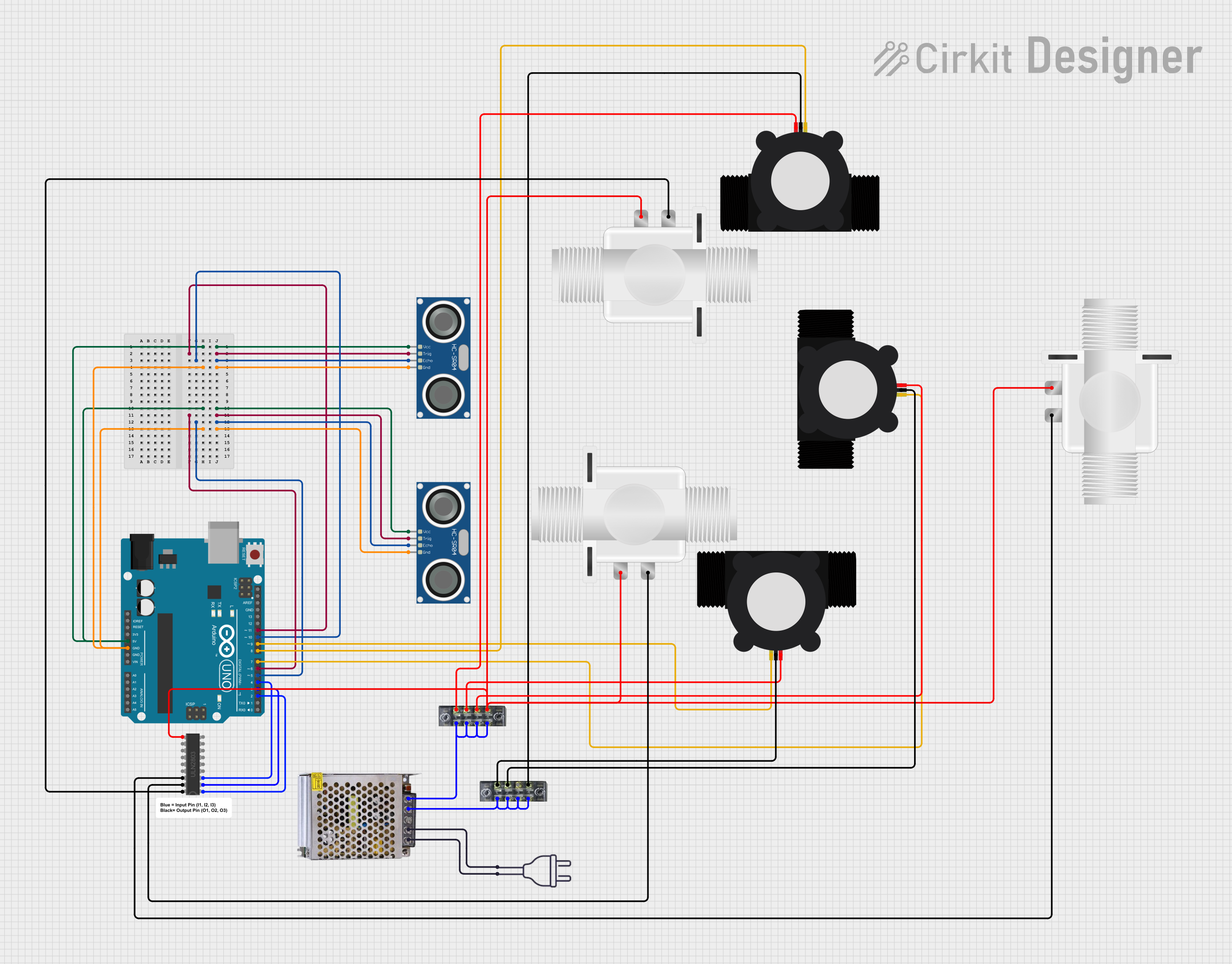
This document provides a detailed overview of a water management system controlled by an Arduino UNO. The system uses ultrasonic sensors to detect objects, water flow sensors to monitor water flow, and solenoid valves to control water flow. The system operates three sets of sensors and valves, ensuring water flow is managed based on object detection and flow rate.
Component List
Plastic Solenoid Valve
- Description: Controls the flow of water.
- Pins: pin1, pin2
ULN2803 Darlington Array
- Description: Used to drive the solenoid valves.
- Pins: I1, I2, I3, I4, I5, I6, I7, I8, O1, O2, O3, O4, O5, O6, O7, O8, GND, COMMON
Arduino UNO
- Description: Microcontroller used to control the entire system.
- Pins: UNUSED, IOREF, Reset, 3.3V, 5V, GND, Vin, A0, A1, A2, A3, A4, A5, SCL, SDA, AREF, D13, D12, D11, D10, D9, D8, D7, D6, D5, D4, D3, D2, D1, D0
HC-SR04 Ultrasonic Sensor
- Description: Used to detect objects.
- Pins: VCC, TRIG, ECHO, GND
YF-S201 Water Flow Meter
- Description: Measures the flow rate of water.
- Pins: SIG, GND, VCC
POWER SUPPLY 12V 5AMP
- Description: Provides power to the system.
- Pins: 220V Positive Pole (AC), 220V Negative Pole (AC), GND, GND (DC), 12V-24V Output (DC)
Terminal Block
- Description: Used for connecting multiple wires.
- Pins: 1, 2, 3, 4, 5, 6, 7, 8
Power 220V
- Description: Provides 220V AC power.
- Pins: hot wire, neutral wire
Wiring Details
Plastic Solenoid Valve
- pin1 connected to ULN2803 Darlington Array pin O1
- pin2 connected to ULN2803 Darlington Array pin O2
ULN2803 Darlington Array
- I1 connected to Arduino UNO pin D2
- I2 connected to Arduino UNO pin D3
- I3 connected to Arduino UNO pin D4
- COMMON connected to Terminal Block pin 7
Arduino UNO
- 5V connected to HC-SR04 Ultrasonic Sensor pin VCC
- GND connected to HC-SR04 Ultrasonic Sensor pin GND
- D11 connected to HC-SR04 Ultrasonic Sensor pin TRIG
- D10 connected to HC-SR04 Ultrasonic Sensor pin ECHO
- D6 connected to HC-SR04 Ultrasonic Sensor pin TRIG
- D5 connected to HC-SR04 Ultrasonic Sensor pin ECHO
- D9 connected to YF-S201 Water Flow Meter pin SIG
- D8 connected to YF-S201 Water Flow Meter pin SIG
- D7 connected to YF-S201 Water Flow Meter pin SIG
- D4 connected to ULN2803 Darlington Array pin I3
- D3 connected to ULN2803 Darlington Array pin I2
- D2 connected to ULN2803 Darlington Array pin I1
HC-SR04 Ultrasonic Sensor
- VCC connected to Arduino UNO pin 5V
- TRIG connected to Arduino UNO pin D11
- ECHO connected to Arduino UNO pin D10
- GND connected to Arduino UNO pin GND
YF-S201 Water Flow Meter
- SIG connected to Arduino UNO pin D9
- GND connected to Terminal Block pin 7
- VCC connected to Terminal Block pin 1
POWER SUPPLY 12V 5AMP
- 220V Positive Pole (AC) connected to Power 220V pin neutral wire
- 220V Negative Pole (AC) connected to Power 220V pin hot wire
- GND (DC) connected to Terminal Block pin 2
- 12V-24V Output (DC) connected to Terminal Block pin 8
Terminal Block
- Pin 1 connected to YF-S201 Water Flow Meter pin VCC
- Pin 2 connected to POWER SUPPLY 12V 5AMP pin GND (DC)
- Pin 3 connected to YF-S201 Water Flow Meter pin GND
- Pin 4 connected to Terminal Block pin 2
- Pin 5 connected to YF-S201 Water Flow Meter pin VCC
- Pin 6 connected to Terminal Block pin 2
- Pin 7 connected to ULN2803 Darlington Array pin COMMON
- Pin 8 connected to POWER SUPPLY 12V 5AMP pin 12V-24V Output (DC)
Power 220V
- hot wire connected to POWER SUPPLY 12V 5AMP pin 220V Negative Pole (AC)
- neutral wire connected to POWER SUPPLY 12V 5AMP pin 220V Positive Pole (AC)
Code Documentation
/*
 * Arduino-Controlled Water Management System with Ultrasonic Sensing and
 * Solenoid Valves
 *
 * This code controls a water management system using an Arduino UNO. It
 * interfaces with ultrasonic sensors to detect objects, water flow sensors to
 * monitor water flow, and solenoid valves to control water flow. The system
 * operates three sets of sensors and valves, ensuring water flow is managed
 * based on object detection and flow rate.
 */

#define TRIG_PIN1 11
#define ECHO_PIN1 10
#define TRIG_PIN2 6
#define ECHO_PIN2 5
#define FS1 9
#define FS2 8
#define FS3 7
#define SV1 2
#define SV2 3
#define SV3 4

const float soundSpeed = 343.0; // Speed of sound in m/s
const float maxDistance = 0.3; // Max distance to check for objects (in meters)

bool isObjectDetected(int trigPin, int echoPin) {
  digitalWrite(trigPin, LOW);
  delayMicroseconds(2);
  digitalWrite(trigPin, HIGH);
  delayMicroseconds(10);
  digitalWrite(trigPin, LOW);
  unsigned long duration = pulseIn(echoPin, HIGH);
  float distance = (duration * soundSpeed) / (2 * 1000); // Convert to meters
  return (distance <= maxDistance);
}

void controlSolenoid(int solenoidPin, bool state) {
  digitalWrite(solenoidPin, state ? HIGH : LOW);
}

void setup() {
  Serial.begin(9600);
  pinMode(ECHO_PIN1, INPUT);
  pinMode(TRIG_PIN1, OUTPUT);
  pinMode(TRIG_PIN2, OUTPUT);
  pinMode(ECHO_PIN2, INPUT);
  pinMode(FS1, INPUT);
  pinMode(FS2, INPUT);
  pinMode(FS3, INPUT);
  pinMode(SV1, OUTPUT);
  pinMode(SV2, OUTPUT);
  pinMode(SV3, OUTPUT);
  digitalWrite(SV1, LOW);
  digitalWrite(SV2, LOW);
  digitalWrite(SV3, LOW);
}

void checkAndControlFlow(int flowSensorPin, int solenoidPin, int trigPin, int echoPin) {
  if (!isObjectDetected(trigPin, echoPin)) {
    Serial.println("No user detected.");
    int flowRate = digitalRead(flowSensorPin);
    controlSolenoid(solenoidPin, flowRate > 0);
  } else {
    controlSolenoid(solenoidPin, LOW);
    Serial.println("User is detected.");
  }
}

void loop() {
  checkAndControlFlow(FS1, SV1, TRIG_PIN1, ECHO_PIN1);
  checkAndControlFlow(FS2, SV2, TRIG_PIN2, ECHO_PIN2);
  if (!isObjectDetected(TRIG_PIN1, ECHO_PIN1) && !isObjectDetected(TRIG_PIN2, ECHO_PIN2)) {