
Wi-Fi Controlled Quad DC Motor Driver System with ESP-8266 and L298N
View and Edit Project In Cirkit Designer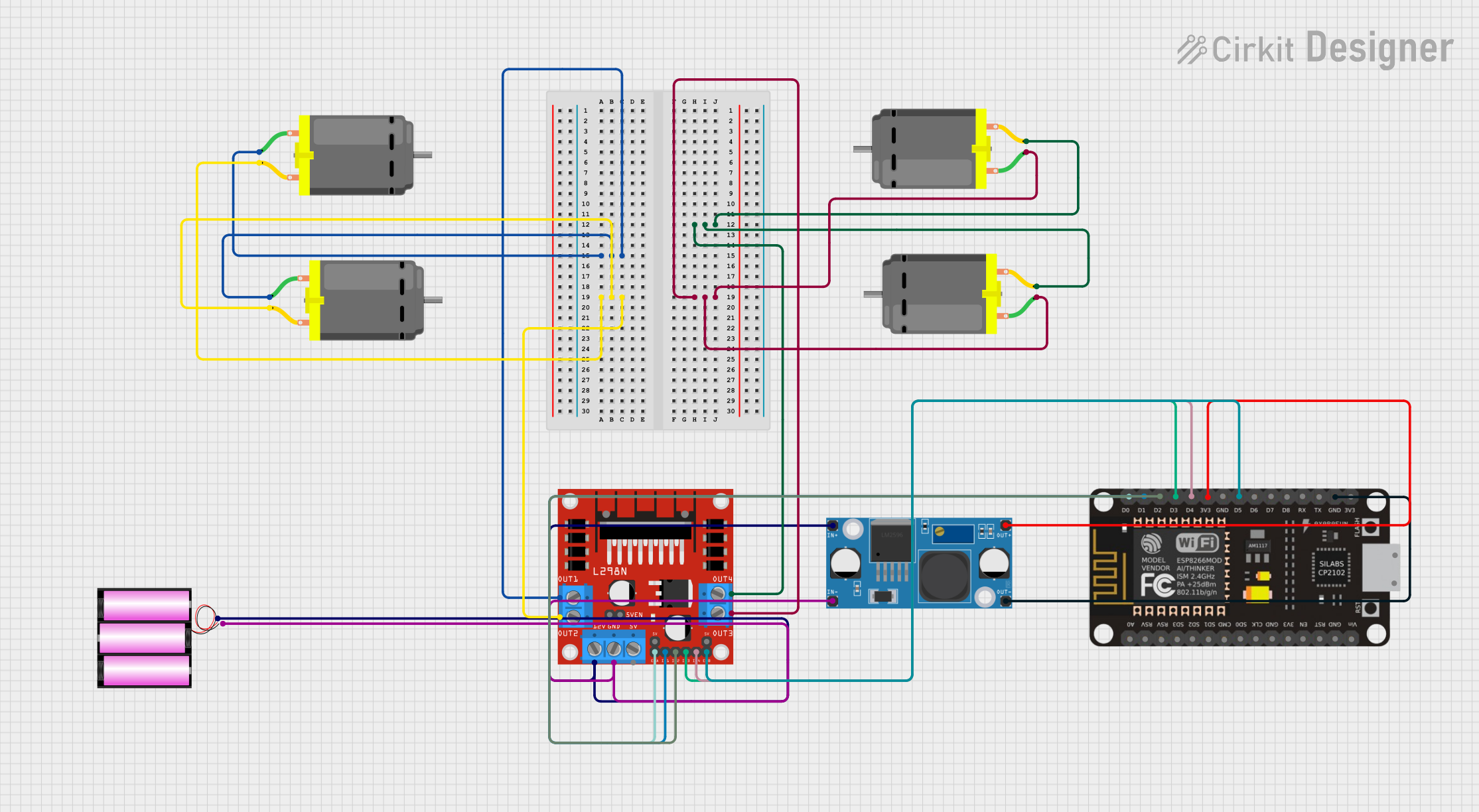
Circuit Documentation
Summary
This document describes a Wi-Fi controlled quad DC motor driver system. The system uses an ESP-8266 microcontroller to control four DC motors via an L298N motor driver. The motors can be controlled through Wi-Fi commands received by the ESP-8266. The system is powered by a 12V battery, and a buck converter is used to step down the voltage for the ESP-8266.
Component List
ESP-8266 Controller
- Description: A Wi-Fi enabled microcontroller used to control the motor driver.
- Pins: A0, RSV, SD3, SD5, SD1, CMD, D0, D1, D2, D3, D4, 3V3, GND, D5, D6, SD0, CLK, RST, EN, D7, D8, RX, TX, Vin, 5V
DC Motor
- Description: A standard DC motor.
- Pins: pin 1, pin 2
LM2956 Buck Converter DC-DC
- Description: A buck converter used to step down the voltage from 12V to 3.3V for the ESP-8266.
- Pins: OUT+, OUT-, IN+, IN-
Battery 12V
- Description: A 12V battery used to power the system.
- Pins: +, -
L298N DC Motor Driver
- Description: A motor driver used to control the DC motors.
- Pins: OUT1, OUT2, 12V, GND, 5V, OUT3, OUT4, 5V-ENA-JMP-I, 5V-ENA-JMP-O, +5V-J1, +5V-J2, ENA, IN1, IN2, IN3, IN4, ENB
Wiring Details
ESP-8266 Controller
- D0 connected to ENA of L298N DC Motor Driver
- D1 connected to IN1 of L298N DC Motor Driver
- D2 connected to IN2 of L298N DC Motor Driver
- D3 connected to IN3 of L298N DC Motor Driver
- D4 connected to IN4 of L298N DC Motor Driver
- D5 connected to ENB of L298N DC Motor Driver
- 3V3 connected to OUT+ of LM2956 Buck Converter DC-DC
- GND connected to OUT- of LM2956 Buck Converter DC-DC
DC Motor 1
- pin 1 connected to OUT1 of L298N DC Motor Driver
- pin 2 connected to OUT2 of L298N DC Motor Driver
DC Motor 2
- pin 1 connected to OUT3 of L298N DC Motor Driver
- pin 2 connected to OUT4 of L298N DC Motor Driver
DC Motor 3
- pin 1 connected to OUT1 of L298N DC Motor Driver
- pin 2 connected to OUT2 of L298N DC Motor Driver
DC Motor 4
- pin 1 connected to OUT3 of L298N DC Motor Driver
- pin 2 connected to OUT4 of L298N DC Motor Driver
LM2956 Buck Converter DC-DC
- IN+ connected to + of Battery 12V
- IN- connected to - of Battery 12V
- OUT+ connected to 3V3 of ESP-8266 Controller
- OUT- connected to GND of ESP-8266 Controller
Battery 12V
- + connected to 12V of L298N DC Motor Driver and IN+ of LM2956 Buck Converter DC-DC
- - connected to GND of L298N DC Motor Driver and IN- of LM2956 Buck Converter DC-DC
L298N DC Motor Driver
- OUT1 connected to pin 1 of DC Motor 1 and pin 1 of DC Motor 3
- OUT2 connected to pin 2 of DC Motor 1 and pin 2 of DC Motor 3
- OUT3 connected to pin 1 of DC Motor 2 and pin 1 of DC Motor 4
- OUT4 connected to pin 2 of DC Motor 2 and pin 2 of DC Motor 4
- ENA connected to D0 of ESP-8266 Controller
- IN1 connected to D1 of ESP-8266 Controller
- IN2 connected to D2 of ESP-8266 Controller
- IN3 connected to D3 of ESP-8266 Controller
- IN4 connected to D4 of ESP-8266 Controller
- ENB connected to D5 of ESP-8266 Controller
- 12V connected to + of Battery 12V
- GND connected to - of Battery 12V
Code Documentation
/*
 * Wi-Fi Controlled Quad DC Motor Driver System
 * This Arduino sketch is designed to control four DC motors using an ESP-8266
 * microcontroller and an L298N motor driver. The motors can be controlled via
 * Wi-Fi commands received by the ESP-8266. The motor driver is connected to
 * the ESP-8266 through digital pins D0 to D5.
 */

// Pin definitions
const int ENA = D0;
const int IN1 = D1;
const int IN2 = D2;
const int IN3 = D3;
const int IN4 = D4;
const int ENB = D5;

void setup() {
  // Initialize serial communication
  Serial.begin(115200);
  // Initialize motor control pins as outputs
  pinMode(ENA, OUTPUT);
  pinMode(IN1, OUTPUT);
  pinMode(IN2, OUTPUT);
  pinMode(IN3, OUTPUT);
  pinMode(IN4, OUTPUT);
  pinMode(ENB, OUTPUT);
  // Initial state of motors (stopped)
  digitalWrite(ENA, LOW);
  digitalWrite(ENB, LOW);
  digitalWrite(IN1, LOW);
  digitalWrite(IN2, LOW);
  digitalWrite(IN3, LOW);
  digitalWrite(IN4, LOW);
}

void loop() {
  // Placeholder for main code to control motors via Wi-Fi
  // Example: Control motor A forward
  digitalWrite(ENA, HIGH);
  digitalWrite(IN1, HIGH);
  digitalWrite(IN2, LOW);
  delay(1000); // Run motor A forward for 1 second
  // Stop motor A
  digitalWrite(ENA, LOW);
  delay(1000); // Wait for 1 second
  // Example: Control motor B backward
  digitalWrite(ENB, HIGH);
  digitalWrite(IN3, LOW);
  digitalWrite(IN4, HIGH);
  delay(1000); // Run motor B backward for 1 second
  // Stop motor B
  digitalWrite(ENB, LOW);
  delay(1000); // Wait for 1 second
}
This code initializes the ESP-8266 microcontroller and sets up the pins connected to the L298N motor driver. The setup function configures the pins as outputs and sets the initial state of the motors to stopped. The loop function contains placeholder code to control the motors via Wi-Fi commands. The example code demonstrates how to control motor A forward and motor B backward.