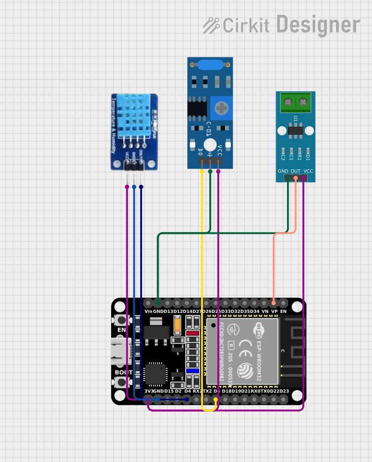
ESP32-Based Environmental and Vibration Monitoring System

Circuit Documentation
Summary of the Circuit
This circuit integrates an ESP32 microcontroller with a DHT11 temperature and humidity sensor, an SW-420 vibration sensor, and an ACS712 current sensor. The ESP32 serves as the central processing unit, interfacing with the sensors to monitor environmental conditions, vibrations, and electrical current flow. The sensors are powered by the ESP32's 3.3V output, and their data outputs are connected to specific GPIO pins on the ESP32 for data acquisition and processing.
Component List
ESP32 (30 pin)
- Description: A powerful microcontroller with Wi-Fi and Bluetooth capabilities, featuring a wide range of GPIO pins for interfacing with various sensors and peripherals.
- Purpose: Acts as the central processing unit for the circuit, reading sensor data and providing wireless connectivity if needed.
DHT11
- Description: A basic, low-cost digital temperature and humidity sensor.
- Purpose: Measures the ambient temperature and humidity levels.
SW-420 Vibration Sensor
- Description: A simple vibration detection sensor that outputs a digital signal when vibration is detected.
- Purpose: Detects vibrations and provides a digital signal to the ESP32 when a vibration occurs.
ACS712 Current Sensor (5A, 20A, 30A)
- Description: A hall-effect-based linear current sensor capable of measuring both AC and DC currents.
- Purpose: Measures the electric current flowing through a conductor and outputs an analog voltage proportional to the current.
Wiring Details
ESP32 (30 pin)
- EN: Enable pin (not connected in this circuit)
- VP: Connected to the analog output of the ACS712 current sensor
- GND: Common ground with DHT11, SW-420 Vibration Sensor, and ACS712 Current Sensor
- 3V3: Powers the DHT11, SW-420 Vibration Sensor, and ACS712 Current Sensor
- D5: Connected to the digital output of the SW-420 Vibration Sensor
- D4: Connected to the data pin of the DHT11
DHT11
- DATA: Connected to GPIO D4 on the ESP32
- GND: Connected to the common ground
- VCC: Powered by the 3.3V output from the ESP32
SW-420 Vibration Sensor
- Digital output: Connected to GPIO D5 on the ESP32
- Ground: Connected to the common ground
- vcc: Powered by the 3.3V output from the ESP32
ACS712 Current Sensor (5A, 20A, 30A)
- OUT: Connected to the analog pin VP on the ESP32
- GND: Connected to the common ground
- VCC: Powered by the 3.3V output from the ESP32
Documented Code
No code has been provided for the microcontroller. The documentation for the code would typically include a description of the functionality, setup and loop functions, and any functions or libraries used to interface with the sensors. Since no code is available, this section cannot be completed. If code becomes available, it should be documented here with comments explaining the purpose and functionality of each section of the code.