Cirkit Designer
Your all-in-one circuit design IDE
Home /
Project Documentation
Arduino UNO Flame Detection System with Buzzer Alert
Circuit Documentation
Summary
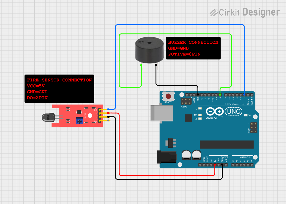
This circuit consists of an Arduino UNO microcontroller, a KY-026 Flame Sensor, and a buzzer. The Arduino UNO is used to read the flame sensor's output and activate the buzzer when a flame is detected. The circuit is powered by the 5V output from the Arduino UNO.
Component List
Arduino UNO
- Description: A microcontroller board based on the ATmega328P.
- Pins: UNUSED, IOREF, Reset, 3.3V, 5V, GND, Vin, A0, A1, A2, A3, A4, A5, SCL, SDA, AREF, D13, D12, D11, D10, D9, D8, D7, D6, D5, D4, D3, D2, D1, D0
Buzzer
- Description: An electronic device that produces a sound when a voltage is applied.
- Pins: PIN, GND
KY-026 Flame Sensor
- Description: A sensor module that detects flame and outputs a digital signal.
- Pins: A0, GND, VCC, D0
Comment
- Description: Placeholder for comments in the circuit design.
- Pins: None
Wiring Details
Arduino UNO
- 5V: Connected to VCC of KY-026 Flame Sensor
- GND: Connected to GND of KY-026 Flame Sensor and GND of Buzzer
- D8: Connected to PIN of Buzzer
- D2: Connected to D0 of KY-026 Flame Sensor
Buzzer
- PIN: Connected to D8 of Arduino UNO
- GND: Connected to GND of Arduino UNO
KY-026 Flame Sensor
- VCC: Connected to 5V of Arduino UNO
- GND: Connected to GND of Arduino UNO
- D0: Connected to D2 of Arduino UNO
Code Documentation
Arduino UNO Code
sketch.ino
void setup() {
  // put your setup code here, to run once:

}

void loop() {
  // put your main code here, to run repeatedly:

}
documentation.txt
This documentation provides a comprehensive overview of the circuit, including a summary, detailed component list, wiring details, and the code used in the Arduino UNO.