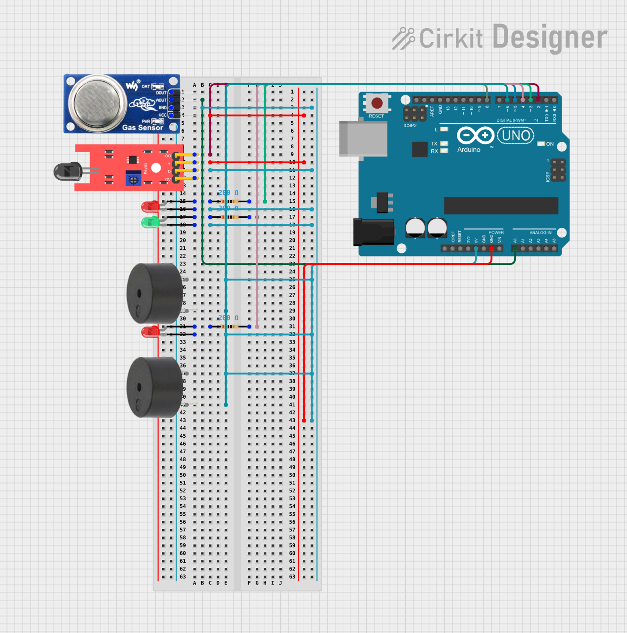
Arduino UNO Based Gas and Flame Detection System with Alert Indicators

Circuit Documentation
Summary
This circuit is designed to monitor environmental conditions, specifically the presence of gas and flames. It utilizes an MQ6 gas sensor and a KY-026 flame sensor to detect hazardous conditions. The circuit provides visual indicators through red and green LEDs and audible alarms using buzzers. The Arduino UNO microcontroller is the central processing unit that reads sensor inputs, controls the LEDs, and activates the buzzers based on predefined threshold values.
Component List
MQ6 Gas Sensor
- Pins: VCC, GND, A0, DO
- Description: A gas sensor used for detecting LPG, butane, propane, methane, alcohol, hydrogen, and smoke.
KY-026 Flame Sensor
- Pins: A0, GND, VCC, D0
- Description: A sensor for detecting fire and other wavelengths of light from approximately 760nm to 1100nm.
LED: Two Pin (red)
- Pins: cathode, anode
- Description: A red light-emitting diode used as an indicator.
LED: Two Pin (green)
- Pins: cathode, anode
- Description: A green light-emitting diode used as an indicator.
Resistor (200 Ohms)
- Pins: pin1, pin2
- Description: A resistor with a resistance of 200 Ohms, used to limit current to the LEDs.
Buzzer
- Pins: PIN, GND
- Description: An electronic buzzer for audible alerts.
Arduino UNO
- Pins: UNUSED, IOREF, Reset, 3.3V, 5V, GND, Vin, A0-A5, SCL, SDA, AREF, D0-D13
- Description: A microcontroller board based on the ATmega328P, used for controlling the sensors, LEDs, and buzzers.
Wiring Details
MQ6 Gas Sensor
- VCC: Connected to 5V power supply.
- GND: Connected to ground.
- A0: Connected to the analog input A0 on the Arduino UNO.
- DO: Not connected in this circuit.
KY-026 Flame Sensor
- VCC: Connected to 5V power supply.
- GND: Connected to ground.
- A0: Not connected in this circuit.
- D0: Connected to digital pin D2 on the Arduino UNO.
LED: Two Pin (red) #1
- Anode: Connected to digital pin D3 through a 200 Ohm resistor.
- Cathode: Connected to ground.
LED: Two Pin (red) #2
- Anode: Connected to digital pin D4 through a 200 Ohm resistor.
- Cathode: Connected to ground.
LED: Two Pin (green)
- Anode: Connected to digital pin D8 through a 200 Ohm resistor.
- Cathode: Connected to ground.
Resistor (200 Ohms) #1
- Pin1: Connected to the anode of the first red LED.
- Pin2: Connected to digital pin D3 on the Arduino UNO.
Resistor (200 Ohms) #2
- Pin1: Connected to the anode of the second red LED.
- Pin2: Connected to digital pin D4 on the Arduino UNO.
Resistor (200 Ohms) #3
- Pin1: Connected to the anode of the green LED.
- Pin2: Connected to digital pin D8 on the Arduino UNO.
Buzzer #1
- PIN: Connected to digital pin D5 on the Arduino UNO.
- GND: Connected to ground.
Buzzer #2
- PIN: Connected to digital pin D6 on the Arduino UNO.
- GND: Connected to ground.
Documented Code
int redLed1 = 3;
int redLed2 = 4;
int greenLed = 8;
int buzzer1 = 5; //PWM (~) pin
int buzzer2 = 6; //PWM (~) pin
int gasPin = A0;
int flamePin = 2;
// Your threshold value
int gasSensorThres = 400;

void setup() {
  pinMode(redLed1, OUTPUT);
  pinMode(redLed2, OUTPUT);
  pinMode(greenLed, OUTPUT);
  pinMode(buzzer1, OUTPUT);
  pinMode(buzzer2, OUTPUT);
  pinMode(gasPin, INPUT);
  pinMode(flamePin, INPUT);
  Serial.begin(9600);
}

void loop() {
  int gasSensor = analogRead(gasPin);
  int flameSensor = digitalRead(flamePin);

  Serial.print("gasPin Value: ");
  Serial.println(gasSensor);
  Serial.print("flamePin Value: ");
  Serial.println(flameSensor);
  delay(1000);

  if (gasSensor > gasSensorThres  && flameSensor==LOW){
    digitalWrite(redLed1, HIGH);
    tone(buzzer1, 5000); //the buzzer sound frequency at 5000 Hz
    digitalWrite(redLed2, HIGH);
    tone(buzzer2, 5000); //the buzzer sound frequency at 5000 Hz
    digitalWrite(greenLed, LOW);
  }
   else if (gasSensor > gasSensorThres)
  {
    digitalWrite(redLed1, HIGH);
    tone(buzzer1, 5000); //the buzzer sound frequency at 5000 Hz
    digitalWrite(redLed2, LOW);
    noTone(buzzer2);
    digitalWrite(greenLed, LOW);
  }
  else if (flameSensor==LOW){ // HIGH MEANS NO FLAME
    digitalWrite(redLed1, LOW);
    noTone(buzzer1);
    digitalWrite(redLed2, HIGH);
    tone(buzzer2, 5000); //the buzzer sound frequency at 5000 Hz
    digitalWrite(greenLed, LOW);
    }

  else
  {
    digitalWrite(redLed1, LOW);
    digitalWrite(redLed2, LOW);
    noTone(buzzer1);
    noTone(buzzer2);
    digitalWrite(greenLed, HIGH);
  }
}
The code is written for the Arduino UNO microcontroller. It initializes the pins connected to the LEDs and buzzers as outputs and the sensor pins as inputs. In the main loop, it reads the gas sensor value and the flame sensor state. Depending on these readings, it turns on the appropriate LEDs and buzzers to alert the user to the presence of gas or flames.