ESP32-Controlled Stepper and Servo Motor System with PCA9685 PWM and ESP32 CAM

Circuit Documentation
Summary
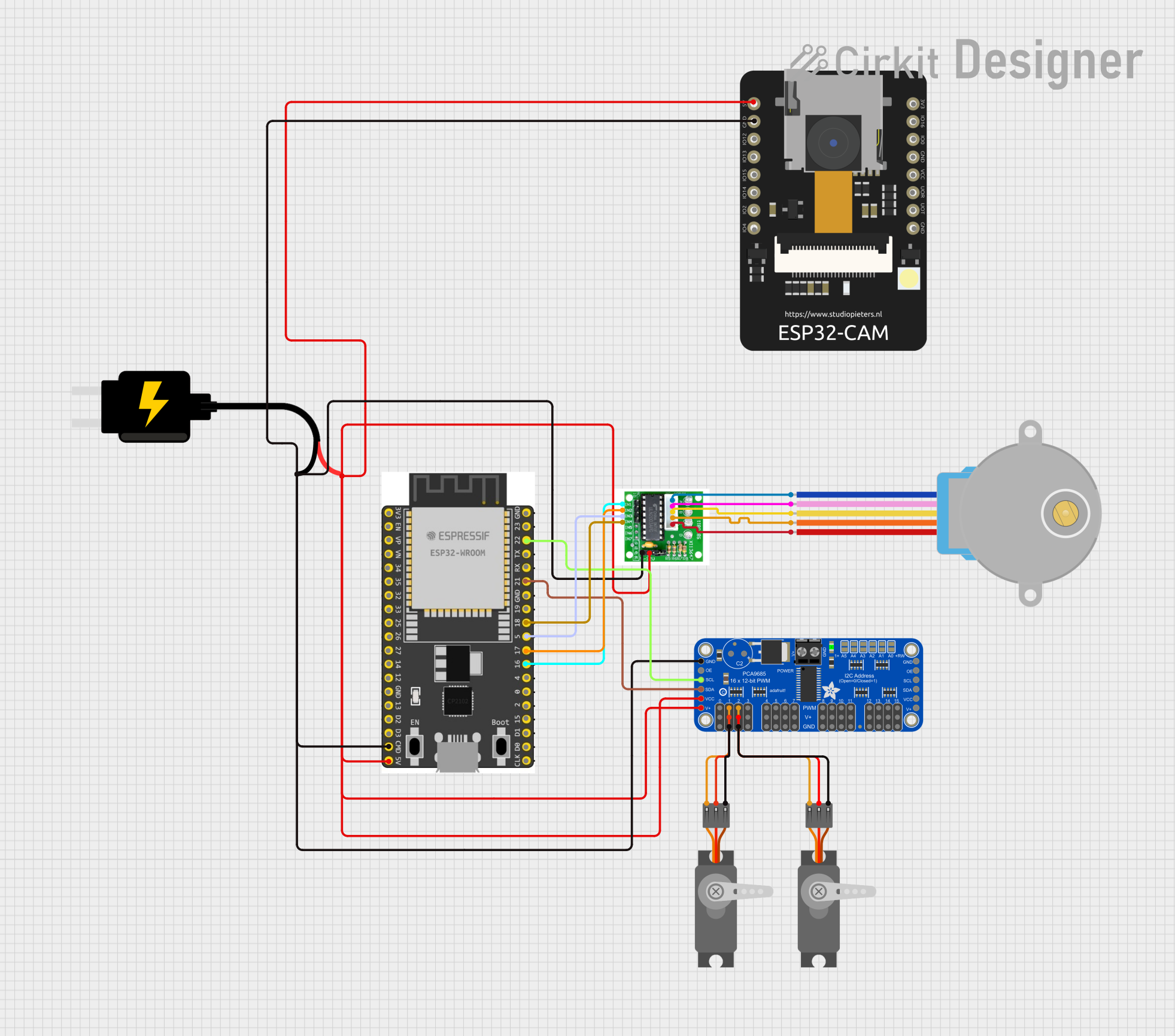
This circuit integrates a variety of components including microcontrollers, a stepper motor, servo motors, a motor driver, and a PWM servo breakout board. The primary control unit is the ESP32 Wroom Dev Kit, which interfaces with the motor driver to control the 28BYJ-48 Stepper Motor and with the Adafruit PCA9685 PWM Servo Breakout to manage two servo motors. The ESP32 CAM module is included, potentially for image capture or video streaming applications. Power is supplied by a DC Source at 5V, which is distributed across the components. Communication between the ESP32 and the PCA9685 is achieved via the I2C protocol, using SDA and SCL lines.
Component List
28BYJ-48 Stepper Motor
- A unipolar stepper motor with a 5-wire interface.
- Pins: BLUE, PINK, YELLOW, ORANGE, RED
ESP 32 Wroom Dev Kit
- A development board with an ESP32 microcontroller, suitable for a variety of IoT applications.
- Pins: 3V3, EN, VP, VN, GPIO 34, GPIO 35, GPIO 32, GPIO 33, GPIO 25, GPIO 26, GPIO 27, GPIO 14, GND, GPIO 13, SD2, SD3, CMD, V5, GPIO 23, GPIO 22, TXD, RXD, GPIO 21, GPIO 19, GPIO 18, GPIO 5, GPIO 17, GPIO 16, GPIO 4, GPIO 0, GPIO 2, GPIO 15, SD1, SD0, CLK
Adafruit PCA9685 PWM Servo Breakout
- A 16-channel, 12-bit PWM Fm+ I2C-bus LED controller optimized for driving servo motors.
- Pins: 5.0V, GND, PWRIN, PWM7 to PWM0, VCC, SDA, SCL, OE, PWM15 to PWM8
DC Source 5V
- A power supply module that provides a regulated 5V output.
- Pins: VCC, GND
Motor Driver
- A driver module capable of controlling stepper motors.
- Pins: IN1, IN2, IN3, IN4, COIL1 to COIL4, VCC, GND
Servo (Wokwi Compatible)
- A standard servo motor for precise angular positioning.
- Pins: GND, V+, PWM
ESP32 CAM
- A small-sized ESP32-based camera module suitable for surveillance or remote monitoring.
- Pins: 5V, GND, GPIO12 to GPIO16, 3.3V, 3.3V / 5V / P_OUT, GPIO3 / RX, GPIO1 / TX
Wiring Details
28BYJ-48 Stepper Motor
- BLUE connected to Motor Driver COIL4
- PINK connected to Motor Driver COIL2
- YELLOW connected to Motor Driver COIL3
- ORANGE connected to Motor Driver COIL1
- RED connected to Motor Driver VCC
ESP 32 Wroom Dev Kit
- 3V3, EN, VP, VN, GPIO 34, GPIO 35, GPIO 32, GPIO 33, GPIO 25, GPIO 26, GPIO 27, GPIO 14, GPIO 13, SD2, SD3, CMD (GND), TXD, RXD, GPIO 19, GPIO 4, GPIO 0, GPIO 2, GPIO 15, SD1, SD0, CLK not connected
- V5 connected to Motor Driver VCC, Adafruit PCA9685 PWM Servo Breakout 5.0V and VCC, ESP32 CAM 5V, DC Source 5V VCC
- GPIO 23 not connected
- GPIO 22 (SCL) connected to Adafruit PCA9685 PWM Servo Breakout SCL
- GPIO 21 (SDA) connected to Adafruit PCA9685 PWM Servo Breakout SDA
- GPIO 18 connected to Motor Driver IN4
- GPIO 5 connected to Motor Driver IN3
- GPIO 17 connected to Motor Driver IN2
- GPIO 16 connected to Motor Driver IN1
Adafruit PCA9685 PWM Servo Breakout
- 5.0V connected to Motor Driver VCC, ESP32 CAM 5V, DC Source 5V VCC, Servo (Wokwi Compatible) V+
- GND connected to Motor Driver GND, ESP32 CAM GND, DC Source 5V GND, Servo (Wokwi Compatible) GND
- PWRIN not connected
- PWM7 to PWM3 not connected
- PWM2 connected to Servo (Wokwi Compatible) PWM
- PWM1 connected to Servo (Wokwi Compatible) PWM
- PWM0 not connected
- VCC connected to Motor Driver VCC, ESP32 CAM 5V, DC Source 5V VCC
- SDA connected to ESP 32 Wroom Dev Kit GPIO 21
- SCL connected to ESP 32 Wroom Dev Kit GPIO 22
- OE not connected
- PWM15 to PWM8 not connected
DC Source 5V
- VCC connected to Motor Driver VCC, Adafruit PCA9685 PWM Servo Breakout 5.0V and VCC, ESP32 CAM 5V
- GND connected to Motor Driver GND, ESP32 CAM GND, Adafruit PCA9685 PWM Servo Breakout GND
Motor Driver
- IN1 to IN4 connected to ESP 32 Wroom Dev Kit GPIO 16, GPIO 17, GPIO 5, GPIO 18 respectively
- COIL1 to COIL4 connected to 28BYJ-48 Stepper Motor ORANGE, BLUE, YELLOW, PINK respectively
- VCC connected to DC Source 5V VCC, Adafruit PCA9685 PWM Servo Breakout 5.0V and VCC, ESP32 CAM 5V
- GND connected to ESP 32 Wroom Dev Kit CMD, Adafruit PCA9685 PWM Servo Breakout GND, ESP32 CAM GND, DC Source 5V GND
Servo (Wokwi Compatible)
- PWM connected to Adafruit PCA9685 PWM Servo Breakout PWM2 or PWM1
- V+ connected to Adafruit PCA9685 PWM Servo Breakout 5.0V
- GND connected to Adafruit PCA9685 PWM Servo Breakout GND
ESP32 CAM
- 5V connected to Motor Driver VCC, Adafruit PCA9685 PWM Servo Breakout 5.0V and VCC, DC Source 5V VCC
- GND connected to Motor Driver GND, ESP 32 Wroom Dev Kit CMD, Adafruit PCA9685 PWM Servo Breakout GND, DC Source 5V GND
- GPIO12 to GPIO16, 3.3V, 3.3V / 5V / P_OUT, GPIO3 / RX, GPIO1 / TX not connected
Documented Code
No code has been provided for the microcontrollers in this circuit. Typically, the code would be documented here, including setup routines, main loops, function definitions, and any libraries used. The code would control the behavior of the microcontrollers, manage communication protocols, and implement the logic for controlling the motors and reading sensors, if any.