Cirkit Designer
Your all-in-one circuit design IDE
Home /
Project Documentation
ESP32-Based Environmental Monitoring and Control System with Gas Detection and Actuators

Circuit Documentation
Summary
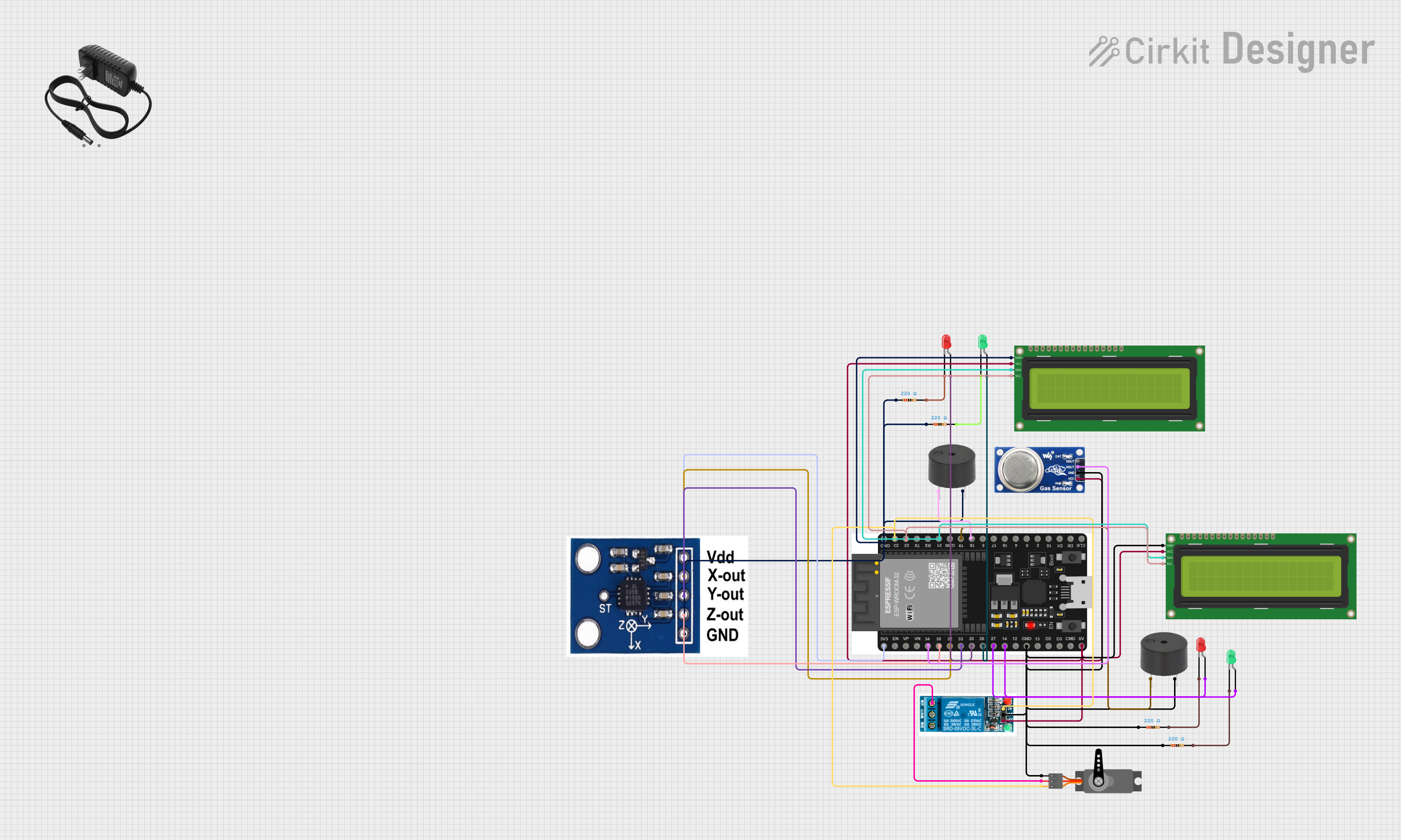
This document provides a detailed overview of an electronic circuit designed to interface various components with an ESP32 microcontroller. The circuit includes input and output devices such as LEDs, a buzzer, an I2C LCD, a servo motor, a relay, sensors like the MQ6 gas sensor and the ADXXL335 accelerometer, and power management components. The ESP32 serves as the central processing unit, controlling the peripherals through its GPIO pins.
Component List
Microcontroller
- ESP32 38 PINS: A microcontroller with a wide range of GPIO pins, including digital and analog inputs, as well as communication interfaces like I2C.
Input Devices
- ADXXL335: A 3-axis accelerometer for measuring acceleration in the X, Y, and Z directions.
- MQ6: A gas sensor designed for detecting LPG, butane, propane, methane, alcohol, hydrogen, and smoke.
Output Devices
- Buzzer: An audible signaling device.
- LED: Two Pin (green): A green light-emitting diode for visual signaling.
- LED: Two Pin (red): A red light-emitting diode for visual signaling.
- 16x2 I2C LCD: A 16-character by 2-line liquid crystal display with an I2C interface for displaying text.
- 5v relay: An electromechanical switch that allows a low-power circuit to control a higher power circuit.
- Servo: A rotary actuator or linear actuator that allows for precise control of angular or linear position.
Power Management
- 12v power supply: Provides a stable 12V power source for the circuit.
Passive Components
- Resistor: A passive two-terminal electrical component that implements electrical resistance as a circuit element.
Wiring Details
Microcontroller (ESP32 38 PINS)
- 3V3: Powers the ADXXL335 accelerometer.
- GND: Common ground for the buzzer, I2C LCD, resistors, ADXXL335, MQ6, servo, and relay.
- GPIO Pins:
- 18: Controls the buzzer.
- 19: Controls another buzzer.
- 14, 26, 27, 25: Drive the anodes of green and red LEDs through current-limiting resistors.
- 34: Reads the analog output from the MQ6 gas sensor.
- 23: Outputs PWM signal to the servo and relay control input.
- 22/SCL, 21/SDA: I2C communication lines connected to the I2C LCD.
- 32, 33, 35: Read the X-OUT, Y-OUT, and Z-OUT from the ADXXL335 accelerometer.
Buzzer
- PIN: Connected to GPIO 18 and 19 of the ESP32 for control.
- GND: Connected to the common ground.
LEDs (Green and Red)
- Anode: Connected to GPIO 14, 26, 27, and 25 of the ESP32 through current-limiting resistors.
- Cathode: Connected to the common ground through current-limiting resistors.
16x2 I2C LCD
- GND: Connected to the common ground.
- VCC: Powered by the 5V/VIN pin of the ESP32.
- SDA, SCL: Connected to the I2C data and clock lines of the ESP32.
5v Relay
- Normally Open: Connected to the servo VCC.
- Common terminal: Not specified in the net list.
- Normally Closed: Not specified in the net list.
- In: Controlled by GPIO 23 of the ESP32.
- GND: Connected to the common ground.
- VCC: Powered by the 5V/VIN pin of the ESP32.
Servo
- GND: Connected to the common ground.
- VCC: Powered through the Normally Open contact of the relay.
- PWM: Controlled by GPIO 23 of the ESP32.
Resistor
- pin1: Connected to the common ground.
- pin2: Connected to the cathodes of the LEDs.
MQ6 Gas Sensor
- VCC: Powered by the 5V/VIN pin of the ESP32.
- GND: Connected to the common ground.
- A0: Analog output connected to GPIO 34 of the ESP32.
- DO: Not specified in the net list.
ADXXL335 Accelerometer
- VCC: Powered by the 3V3 pin of the ESP32.
- GND: Connected to the common ground.
- X-OUT, Y-OUT, Z-OUT: Connected to GPIO 32, 33, and 35 of the ESP32 respectively.
Documented Code
void setup() {
  // put your setup code here, to run once:

}

void loop() {
  // put your main code here, to run repeatedly:

}
The provided code is a template with empty setup() and loop() functions, which are the entry points for initializing the circuit and running the main code, respectively. The actual implementation will depend on the specific application and logic required to control the components in the circuit.