
ESP32-Based Environmental Monitoring System with I2C LCD Display
View and Edit Project In Cirkit Designer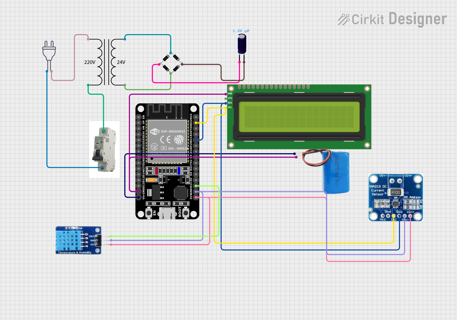
Circuit Documentation
Summary
This circuit is designed to interface an ESP32 microcontroller with an I2C LCD screen, a DHT11 temperature and humidity sensor, a current sensor, and a power supply system that includes a 5V battery, a 220V power source, a Miniature Circuit Breaker (MCB), a power transformer (220V to 24V), a bridge rectifier, and an electrolytic capacitor. The ESP32 reads data from the DHT11 sensor and the current sensor and displays information on the I2C LCD screen. The power supply system converts 220V AC to a regulated 5V DC supply for the ESP32 and other components.
Component List
ESP32 (30 pin)
- A 30-pin microcontroller with WiFi and Bluetooth capabilities.
- Pins: EN, VP, VN, D34, D35, D32, D33, D25, D26, D27, D14, D12, D13, GND, Vin, D23, D22, TX0, RX0, D21, D19, D18, D5, TX2, RX2, D4, D2, D15, 3V3.
I2C LCD 16x2 Screen
- A 16x2 character LCD display with an I2C interface.
- Pins: SCL, SDA, VCC (5V), GND, VDD, VO, RS, RW, E, D0, D1, D2, D3, D4, D5, D6, D7, BLA, BLK.
5V Battery
- A battery providing a 5V power supply.
- Pins: Positive, Negative.
MCB (Miniature Circuit Breaker)
- A safety device used to protect the circuit from overcurrent.
- Pins: IN, OUT.
Current Sensor
- A sensor used to measure the current flowing through a conductor.
- Pins: Vin +, Vin -, Vcc, Gnd, SCl, Sda.
DHT11
- A digital temperature and humidity sensor.
- Pins: DATA, GND, VCC.
Power 220V
- The main AC power supply.
- Pins: Hot wire, Neutral wire.
Bridge Rectifier
- A device that converts AC to DC.
- Pins: Source_in-, Source_out-, Source_out+, Source_in+.
Power Transformer (220V to 24V)
- A transformer used to step down the voltage from 220V to 24V.
- Pins: 2 - Primary, 1 - Primary, 3 - Secondary, 4 - Secondary.
Electrolytic Capacitor
- A capacitor used for filtering and smoothing the DC supply.
- Pins: -, +.
- Properties: Capacitance - 1µF (0.000001 Farads).
Wiring Details
ESP32 (30 pin)
- GND connected to the negative terminal of the 5V battery and GND of the I2C LCD screen.
- Vin connected to the positive terminal of the 5V battery.
- D22 (SCL) connected to SCL of the I2C LCD screen and SCl of the current sensor.
- D21 (SDA) connected to SDA of the I2C LCD screen and Sda of the current sensor.
- D15 connected to DATA of the DHT11 sensor.
- 3V3 connected to VCC of the DHT11 sensor and Vin + of the current sensor.
I2C LCD 16x2 Screen
- SCL connected to D22 of the ESP32 and SCl of the current sensor.
- SDA connected to D21 of the ESP32 and Sda of the current sensor.
- GND connected to the negative terminal of the 5V battery and GND of the ESP32.
5V Battery
- Positive terminal connected to Vin of the ESP32.
- Negative terminal connected to GND of the ESP32, GND of the I2C LCD screen, and GND of the DHT11 sensor.
MCB
- IN connected to the hot wire of the 220V power.
- OUT connected to the primary side of the Power Transformer (220V to 24V).
Current Sensor
- SCl connected to SCL of the I2C LCD screen and D22 of the ESP32.
- Sda connected to SDA of the I2C LCD screen and D21 of the ESP32.
- Vin + connected to 3V3 of the ESP32 and VCC of the DHT11 sensor.
- Vin - connected to GND of the ESP32 and GND of the DHT11 sensor.
DHT11
- DATA connected to D15 of the ESP32.
- GND connected to GND of the ESP32 and Vin - of the current sensor.
- VCC connected to 3V3 of the ESP32 and Vin + of the current sensor.
Power Transformer (220V to 24V)
- 2 - Primary connected to OUT of the MCB.
- 1 - Primary connected to the neutral wire of the 220V power.
- 3 - Secondary connected to Source_in- of the Bridge Rectifier.
- 4 - Secondary connected to Source_in+ of the Bridge Rectifier.
Bridge Rectifier
- Source_in- connected to 3 - Secondary of the Power Transformer.
- Source_out- connected to - of the Electrolytic Capacitor.
- Source_out+ connected to + of the Electrolytic Capacitor.
- Source_in+ connected to 4 - Secondary of the Power Transformer.
Electrolytic Capacitor
-
- connected to Source_out- of the Bridge Rectifier.
-
- connected to Source_out+ of the Bridge Rectifier.
Documented Code
/*
 * ESP32 Interface with I2C LCD and IR Sensor
 * This code reads the status of an IR sensor and displays it on an I2C LCD.
 */

#include <Wire.h>
#include <LiquidCrystal_I2C.h>

// Define the I2C address for the LCD
#define I2C_ADDR 0x27
#define LCD_COLUMNS 16
#define LCD_ROWS 2

// Initialize the LCD
LiquidCrystal_I2C lcd(I2C_ADDR, LCD_COLUMNS, LCD_ROWS);

// Define the IR sensor pin
const int irSensorPin = 2;

void setup() {
  // Initialize the LCD
  lcd.begin();
  lcd.backlight();
  lcd.setCursor(0, 0);
  lcd.print("IR Sensor Status:");

  // Initialize the IR sensor pin
  pinMode(irSensorPin, INPUT);
}

void loop() {
  // Read the IR sensor value
  int irValue = digitalRead(irSensorPin);

  // Display the IR sensor status on the LCD
  lcd.setCursor(0, 1);
  if (irValue == HIGH) {
    lcd.print("Object Detected ");
  } else {
    lcd.print("No Object       ");
  }

  // Small delay to avoid flickering
  delay(200);
}
Note: The code provided is for interfacing an IR sensor with the ESP32 and displaying its status on an I2C LCD. However, the IR sensor is not listed in the components provided. The pin irSensorPin is defined as 2, which does not correspond to any pin labels on the ESP32 provided in the parts list. This discrepancy should be addressed for proper functionality of the circuit.