
Arduino UNO Based Environmental Monitoring System with GSM Reporting
View and Edit Project In Cirkit Designer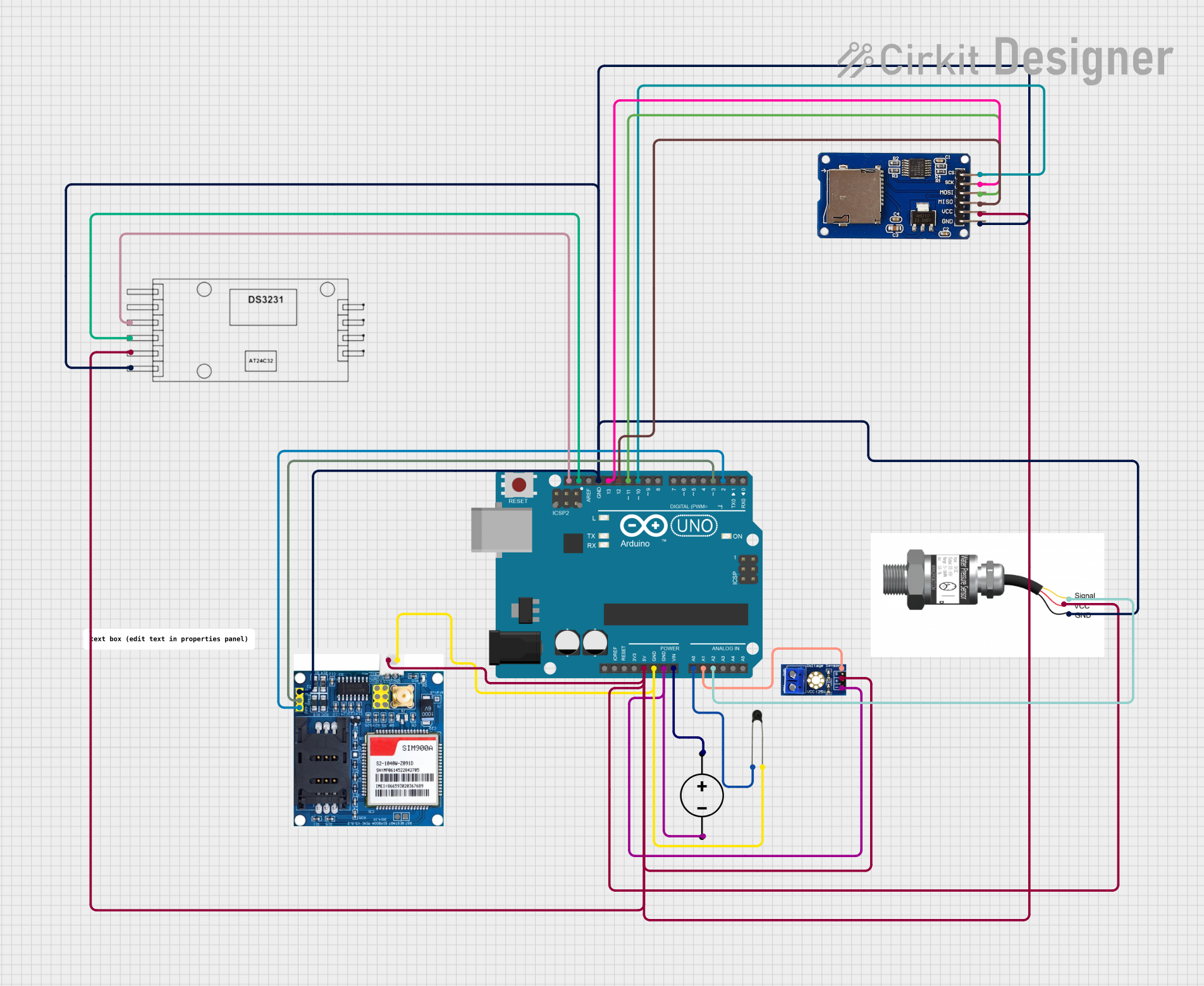
Circuit Documentation
Summary
This document provides a detailed overview of a circuit that includes an Arduino UNO as the central microcontroller, interfaced with various sensors and modules including a DC Power Supply, NTC (thermistor), voltage sensor, pressure sensor, SIM900A GSM module, RTC DS3231 (Real-Time Clock), and an SD card module. The circuit is designed to monitor temperature, voltage, and pressure, log data to an SD card, maintain accurate timekeeping, and communicate over GSM.
Component List
Arduino UNO
- Microcontroller board based on the ATmega328P
- It has 14 digital input/output pins, 6 analog inputs, a 16 MHz quartz crystal, a USB connection, a power jack, an ICSP header, and a reset button.
DC Power Supply
- Provides power to the circuit
- It has a ground (GND) and a positive voltage (V+) output.
NTC (Negative Temperature Coefficient Thermistor)
- A temperature sensor that decreases its resistance with an increase in temperature.
Voltage Sensor DC
- Measures DC voltage in the circuit
- It has a signal output, VCC, and GND pins.
Pressure Sensor
- Measures pressure in the environment
- It has a signal output and power supply pins (+ and -).
SIM900A GSM Module
- Provides GSM/GPRS communication capabilities
- It has pins for power supply (VCC and GND), communication (TXD and RXD), and control (RESTART and RESET).
RTC DS3231 (Real-Time Clock)
- Maintains accurate timekeeping even when the main microcontroller is powered off
- It has SCL and SDA for I2C communication, VCC for power, and GND.
SD Card Module
- Used for data logging onto an SD card
- It has pins for SPI communication (MISO, MOSI, SCK, CS) and power supply (VCC and GND).
Wiring Details
Arduino UNO
5Vconnected to the VCC of SD card module, SIM900A GSM module, voltage sensor, pressure sensor, and RTC DS3231GNDconnected to the GND of all other componentsVinconnected to the V+ of the DC Power SupplyA0connected to the A0 of NTCA1connected to the signal of voltage sensor dcA2connected to the signal of pressure sensorSCLconnected to the SCL of RTC DS3231SDAconnected to the SDA of RTC DS3231D13connected to the SCK of SD card moduleD12connected to the MISO of SD card moduleD11connected to the MOSI of SD card moduleD10connected to the CS of SD card moduleD3connected to the RXD of SIM900A GSM moduleD2connected to the TXD of SIM900A GSM module
DC Power Supply
GNDconnected to the GND of Arduino UNOV+connected to the Vin of Arduino UNO
NTC
A0connected to the A0 of Arduino UNOA1connected to the GND of Arduino UNO
Voltage Sensor DC
signalconnected to the A1 of Arduino UNOvccconnected to the 5V of Arduino UNOgndconnected to the GND of Arduino UNO
Pressure Sensor
signalconnected to the A2 of Arduino UNO+connected to the 5V of Arduino UNO-connected to the GND of Arduino UNO
SIM900A GSM Module
VCC/ 4-5Vconnected to the 5V of Arduino UNOGND/0Vconnected to the GND of Arduino UNORXDconnected to the D3 of Arduino UNOTXDconnected to the D2 of Arduino UNO
RTC DS3231
SCLconnected to the SCL of Arduino UNOSDAconnected to the SDA of Arduino UNOVCCconnected to the 5V of Arduino UNOGNDconnected to the GND of Arduino UNO
SD Card Module
GNDconnected to the GND of Arduino UNOVCCconnected to the 5V of Arduino UNOMISOconnected to the D12 of Arduino UNOMOSIconnected to the D11 of Arduino UNOSCKconnected to the D13 of Arduino UNOCSconnected to the D10 of Arduino UNO
Documented Code
Arduino UNO Code (sketch.ino)
void setup() {
  // put your setup code here, to run once:

}

void loop() {
  // put your main code here, to run repeatedly:

}
Note: The provided code is a template and does not include specific functionality. It should be populated with the necessary setup and loop code to control the connected components and perform the desired tasks.