Cirkit Designer
Your all-in-one circuit design IDE
Home /
Project Documentation
Dual RTD Temperature Sensing with Arduino UNO
Circuit Documentation
Summary
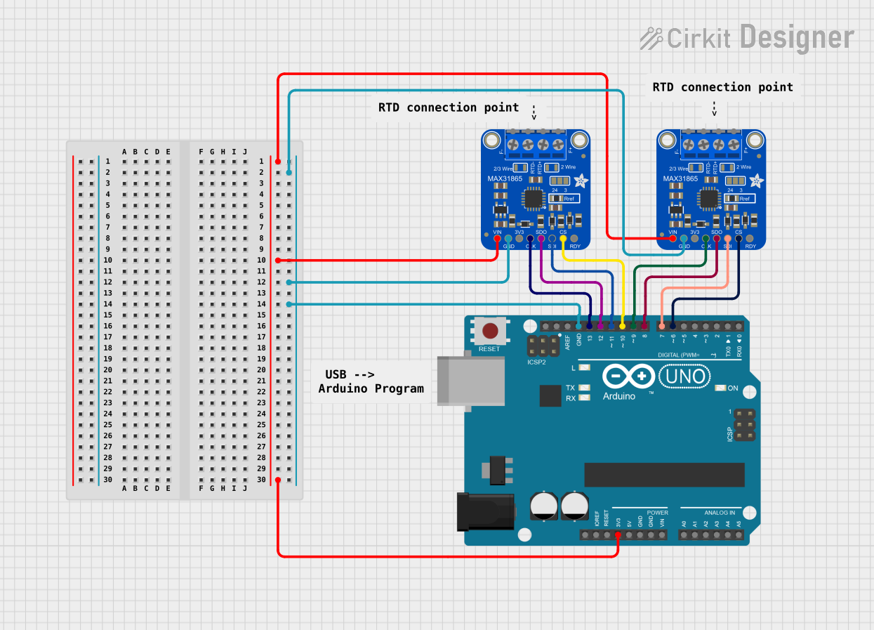
This circuit integrates an Arduino UNO microcontroller with two Adafruit MAX31865 RTD Sensor Breakouts. The Arduino UNO is responsible for controlling the sensors and processing the data from the RTD sensors. The MAX31865 is a precision temperature sensor breakout board that reads Resistance Temperature Detectors (RTDs). The circuit is designed to measure temperature with high accuracy by using the RTD sensors interfaced with the Arduino UNO through SPI communication.
Component List
Arduino UNO
- Description: A microcontroller board based on the ATmega328P.
- Purpose: Acts as the central processing unit for controlling the RTD sensors and handling SPI communication.
- Pins: UNUSED, IOREF, Reset, 3.3V, 5V, GND, Vin, A0-A5, SCL, SDA, AREF, D13-D0.
Adafruit MAX31865 RTD Sensor Breakout #1
- Description: A breakout board for reading RTD sensors with an SPI interface.
- Purpose: Measures temperature with high accuracy.
- Pins: VIN, GND, 3.3V, SCLK, SDO, SDI, CS, DRDY, FORCE+, RTDIN+, RTDIN-, FORCE-.
Adafruit MAX31865 RTD Sensor Breakout #2
- Description: A breakout board for reading RTD sensors with an SPI interface.
- Purpose: Measures temperature with high accuracy.
- Pins: VIN, GND, 3.3V, SCLK, SDO, SDI, CS, DRDY, FORCE+, RTDIN+, RTDIN-, FORCE-.
Wiring Details
Arduino UNO
- 3.3V connected to VIN of both Adafruit MAX31865 RTD Sensor Breakouts.
- GND connected to GND of both Adafruit MAX31865 RTD Sensor Breakouts.
- D13 connected to SCLK of Adafruit MAX31865 RTD Sensor Breakout #1.
- D12 connected to SDO of Adafruit MAX31865 RTD Sensor Breakout #1.
- D11 connected to SDI of Adafruit MAX31865 RTD Sensor Breakout #1.
- D10 connected to CS of Adafruit MAX31865 RTD Sensor Breakout #1.
- D9 connected to SCLK of Adafruit MAX31865 RTD Sensor Breakout #2.
- D8 connected to SDO of Adafruit MAX31865 RTD Sensor Breakout #2.
- D7 connected to SDI of Adafruit MAX31865 RTD Sensor Breakout #2.
- D6 connected to CS of Adafruit MAX31865 RTD Sensor Breakout #2.
Adafruit MAX31865 RTD Sensor Breakout #1
- VIN connected to 3.3V of Arduino UNO.
- GND connected to GND of Arduino UNO.
- SCLK connected to D13 of Arduino UNO.
- SDO connected to D12 of Arduino UNO.
- SDI connected to D11 of Arduino UNO.
- CS connected to D10 of Arduino UNO.
Adafruit MAX31865 RTD Sensor Breakout #2
- VIN connected to 3.3V of Arduino UNO.
- GND connected to GND of Arduino UNO.
- SCLK connected to D9 of Arduino UNO.
- SDO connected to D8 of Arduino UNO.
- SDI connected to D7 of Arduino UNO.
- CS connected to D6 of Arduino UNO.
Documented Code
Arduino UNO Code (sketch.ino)
void setup() {
  // put your setup code here, to run once:

}

void loop() {
  // put your main code here, to run repeatedly:

}
Note: The provided code is a template and does not include specific instructions for interacting with the Adafruit MAX31865 RTD Sensor Breakouts. The user should implement the SPI communication and sensor reading logic within the setup() and loop() functions.