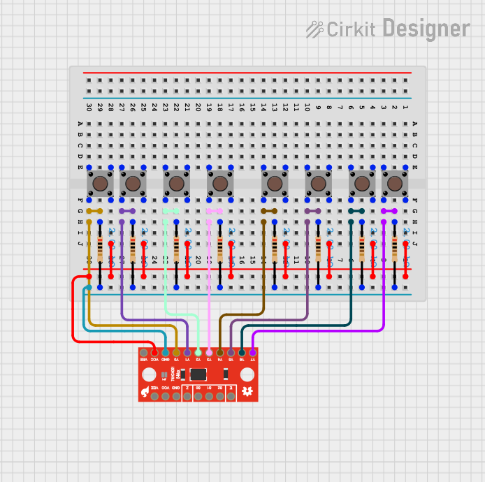
8-Channel Multiplexer with Pushbutton Inputs and Resistor Network

Circuit Documentation
Summary
This circuit consists of a SparkFun 74HC4051 8-Channel Multiplexer Breakout, multiple pushbuttons, and resistors. The pushbuttons are connected to the multiplexer through resistors, allowing for the selection of different input channels. The circuit is designed to interface multiple pushbuttons with a single input pin on a microcontroller or other digital logic device.
Component List
SparkFun 74HC4051 8-Channel Multiplexer Breakout
- Description: An 8-channel analog multiplexer/demultiplexer.
- Pins: Y7, Y6, Y5, Y4, Y3, Y2, Y1, Y0, GND, VCC, VEE, !E!, S2, S1, S0, Z
Pushbutton
- Description: A simple pushbutton switch.
- Pins: Pin 3 (out), Pin 4 (out), Pin 1 (in), Pin 2 (in)
Resistor
- Description: A resistor with a resistance of 2000 Ohms.
- Pins: pin1, pin2
Wiring Details
SparkFun 74HC4051 8-Channel Multiplexer Breakout
VCC is connected to:
- Pin 4 (out) of all pushbuttons
GND is connected to:
- pin2 of all resistors
Y7 is connected to:
- pin1 of a resistor
- Pin 2 (in) of a pushbutton
Y6 is connected to:
- pin1 of a resistor
- Pin 2 (in) of a pushbutton
Y5 is connected to:
- pin1 of a resistor
- Pin 2 (in) of a pushbutton
Y4 is connected to:
- pin1 of a resistor
- Pin 2 (in) of a pushbutton
Y3 is connected to:
- pin1 of a resistor
- Pin 2 (in) of a pushbutton
Y2 is connected to:
- pin1 of a resistor
- Pin 2 (in) of a pushbutton
Y1 is connected to:
- pin1 of a resistor
- Pin 2 (in) of a pushbutton
Y0 is connected to:
- pin1 of a resistor
- Pin 2 (in) of a pushbutton
Pushbutton
Pin 4 (out) is connected to:
- VCC of the SparkFun 74HC4051 8-Channel Multiplexer Breakout
Pin 2 (in) is connected to:
- pin1 of a resistor
- Corresponding Y pin of the SparkFun 74HC4051 8-Channel Multiplexer Breakout
Resistor
pin1 is connected to:
- Pin 2 (in) of a pushbutton
- Corresponding Y pin of the SparkFun 74HC4051 8-Channel Multiplexer Breakout
pin2 is connected to:
- GND of the SparkFun 74HC4051 8-Channel Multiplexer Breakout
Documented Code
There is no code provided for this circuit.