
Arduino Nano-Based Environmental Monitoring System with OLED Display
View and Edit Project In Cirkit Designer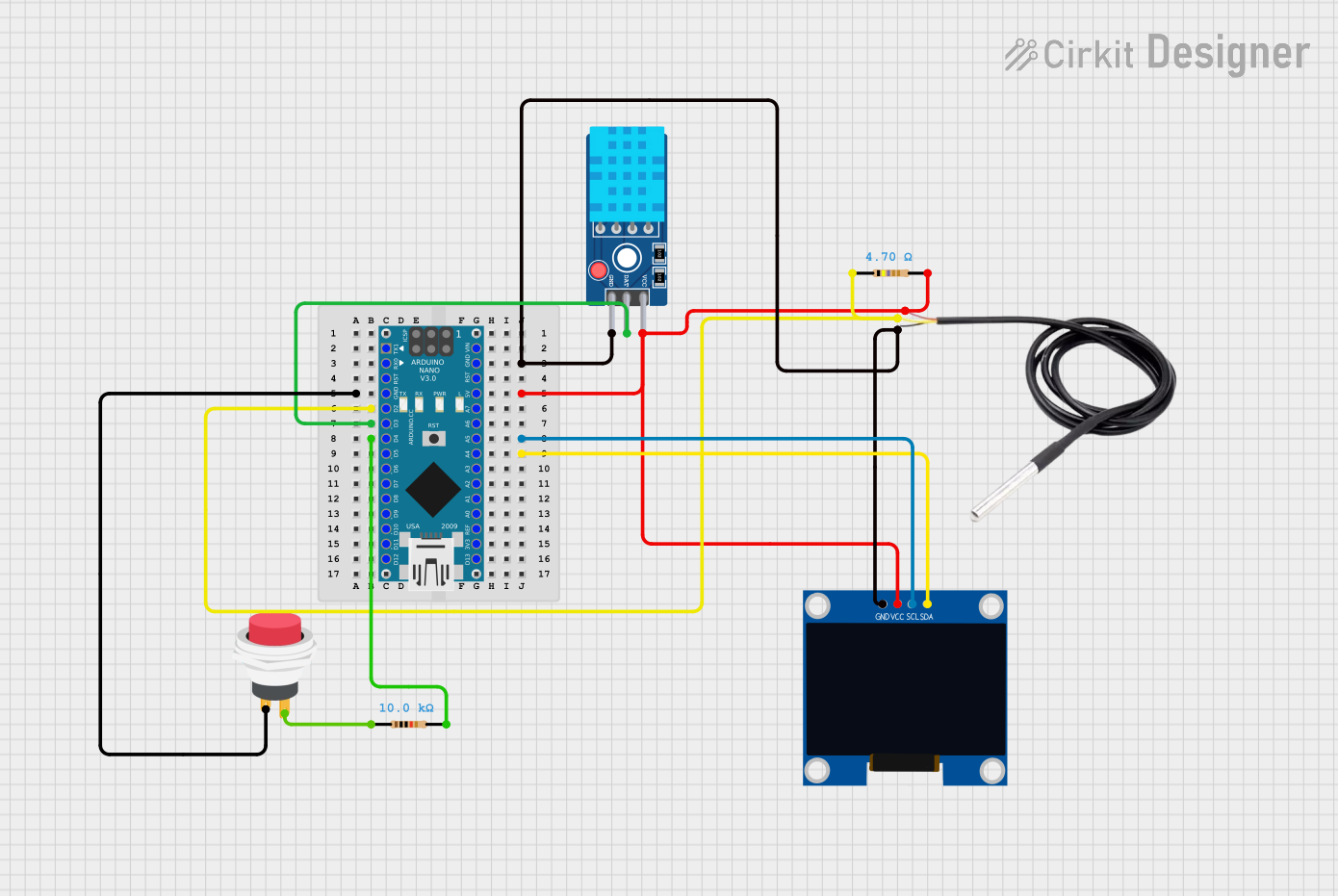
Circuit Documentation
Summary
This circuit integrates an Arduino Nano microcontroller with a DS18B20 temperature sensor, a DHT11 humidity and temperature sensor, a 128x64 OLED display, a 10k Ohm resistor, a 4.7 Ohm resistor, and a 2-pin push switch. The Arduino Nano serves as the central processing unit, interfacing with the sensors to collect temperature and humidity data, and displaying the information on the OLED screen. The resistors are used for pull-up configurations and current limiting, while the push switch provides user input capability.
Component List
Arduino Nano
- Description: A compact microcontroller board based on the ATmega328P.
- Pins: D1/TX, D0/RX, RESET, GND, D2 to D13, VIN, 5V, A0 to A7, AREF, 3V3.
DS18B20 Temperature Sensor
- Description: A digital temperature sensor providing 9-bit to 12-bit Celsius temperature measurements.
- Pins: Signal, GND, VCC.
DHT11 Sensor V2
- Description: A basic, ultra low-cost digital temperature and humidity sensor.
- Pins: GND, DAT, VCC.
128x64 OLED Display (I2C IIC SPI Serial)
- Description: A small display for showing graphics and text.
- Pins: GND, SDA, SCL, VCC.
Resistor (10k Ohms)
- Description: A resistor with a resistance of 10,000 Ohms, commonly used as a pull-up resistor.
- Pins: Pin1, Pin2.
Resistor (4.7 Ohms)
- Description: A resistor with a resistance of 4.7 Ohms, used for current limiting or low-value pull-up/down.
- Pins: Pin1, Pin2.
2Pin Push Switch
- Description: A simple push-to-make switch.
- Pins: Input +, Output +.
Wiring Details
Arduino Nano
- GND: Connected to GND pins of DS18B20, DHT11 Sensor V2, 128x64 OLED Display, and one side of the 2Pin Push Switch.
- 5V: Powers the DS18B20, DHT11 Sensor V2, and 128x64 OLED Display. Also connected to one side of the 4.7 Ohm resistor.
- D2: Connected to the signal pin of DS18B20 with a 4.7 Ohm pull-up resistor.
- D3: Connected to the DAT pin of DHT11 Sensor V2.
- D4: Connected to one side of the 10k Ohm resistor.
- A4 (SDA): Connected to the SDA pin of the 128x64 OLED Display.
- A5 (SCL): Connected to the SCL pin of the 128x64 OLED Display.
DS18B20 Temperature Sensor
- Signal: Connected to D2 on the Arduino Nano with a 4.7 Ohm pull-up resistor to 5V.
- GND: Connected to GND on the Arduino Nano.
- VCC: Connected to 5V on the Arduino Nano.
DHT11 Sensor V2
- DAT: Connected to D3 on the Arduino Nano.
- GND: Connected to GND on the Arduino Nano.
- VCC: Connected to 5V on the Arduino Nano.
128x64 OLED Display (I2C IIC SPI Serial)
- SDA: Connected to A4 on the Arduino Nano.
- SCL: Connected to A5 on the Arduino Nano.
- GND: Connected to GND on the Arduino Nano.
- VCC: Connected to 5V on the Arduino Nano.
Resistor (10k Ohms)
- Pin1: Connected to D4 on the Arduino Nano.
- Pin2: Connected to the Output + pin of the 2Pin Push Switch.
Resistor (4.7 Ohms)
- Pin1: Connected to the signal pin of DS18B20.
- Pin2: Connected to 5V on the Arduino Nano.
2Pin Push Switch
- Input +: Connected to GND on the Arduino Nano.
- Output +: Connected to one side of the 10k Ohm resistor.
Documented Code
Arduino Nano Code (sketch.ino)
void setup() {
  // put your setup code here, to run once:

}

void loop() {
  // put your main code here, to run repeatedly:

}
Note: The provided code is a template and does not contain any functional code. It needs to be populated with the logic for reading sensors, processing data, and controlling the OLED display.