
Arduino UNO-Based Burnt Toast Detector with Servo and Buzzer
View and Edit Project In Cirkit Designer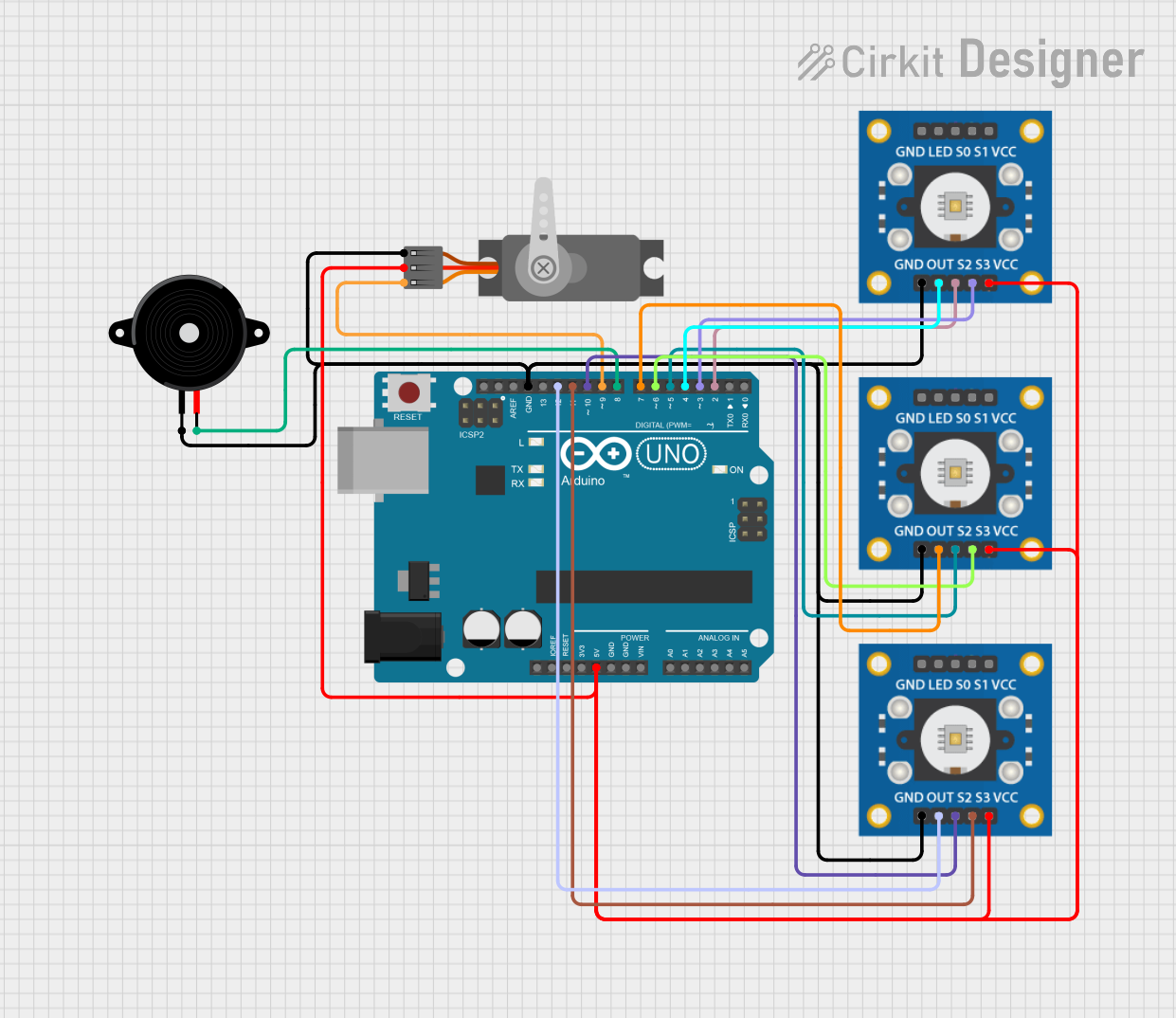
Circuit Documentation
Summary
This circuit is designed to detect burnt toast using three TCS3200 color sensors. The Arduino UNO microcontroller processes the sensor data and controls a servo motor and a piezo speaker. When burnt toast is detected, the servo motor moves, and the piezo speaker emits a sound.
Component List
Arduino UNO
- Description: A microcontroller board based on the ATmega328P.
- Pins: UNUSED, IOREF, Reset, 3.3V, 5V, GND, Vin, A0, A1, A2, A3, A4, A5, SCL, SDA, AREF, D13, D12, D11, D10, D9, D8, D7, D6, D5, D4, D3, D2, D1, D0
Servo (Wokwi Compatible)
- Description: A servo motor compatible with Wokwi.
- Pins: GND, V+, PWM
Piezo Speaker
- Description: A piezoelectric speaker for sound output.
- Pins: pin1, pin2
TCS3200 Color Sensor (Sensor 1)
- Description: A color sensor that can detect RGB values.
- Pins: GND, OUT, S2, S3, VCC, LED, S0, S1
TCS3200 Color Sensor (Sensor 2)
- Description: A color sensor that can detect RGB values.
- Pins: GND, OUT, S2, S3, VCC, LED, S0, S1
TCS3200 Color Sensor (Sensor 3)
- Description: A color sensor that can detect RGB values.
- Pins: GND, OUT, S2, S3, VCC, LED, S0, S1
Wiring Details
Arduino UNO
- 5V: Connected to VCC of all TCS3200 sensors and V+ of the Servo.
- GND: Connected to GND of all TCS3200 sensors, GND of the Servo, and pin1 of the Piezo Speaker.
- D12: Connected to OUT of TCS3200 (Sensor 3).
- D11: Connected to S3 of TCS3200 (Sensor 3).
- D10: Connected to S2 of TCS3200 (Sensor 3).
- D9: Connected to PWM of the Servo.
- D8: Connected to pin2 of the Piezo Speaker.
- D7: Connected to OUT of TCS3200 (Sensor 2).
- D6: Connected to S3 of TCS3200 (Sensor 2).
- D5: Connected to S2 of TCS3200 (Sensor 2).
- D4: Connected to OUT of TCS3200 (Sensor 1).
- D3: Connected to S3 of TCS3200 (Sensor 1).
- D2: Connected to S2 of TCS3200 (Sensor 1).
Servo (Wokwi Compatible)
- V+: Connected to 5V of Arduino UNO.
- GND: Connected to GND of Arduino UNO.
- PWM: Connected to D9 of Arduino UNO.
Piezo Speaker
- pin1: Connected to GND of Arduino UNO.
- pin2: Connected to D8 of Arduino UNO.
TCS3200 Color Sensor (Sensor 1)
- VCC: Connected to 5V of Arduino UNO.
- GND: Connected to GND of Arduino UNO.
- OUT: Connected to D4 of Arduino UNO.
- S2: Connected to D2 of Arduino UNO.
- S3: Connected to D3 of Arduino UNO.
TCS3200 Color Sensor (Sensor 2)
- VCC: Connected to 5V of Arduino UNO.
- GND: Connected to GND of Arduino UNO.
- OUT: Connected to D7 of Arduino UNO.
- S2: Connected to D5 of Arduino UNO.
- S3: Connected to D6 of Arduino UNO.
TCS3200 Color Sensor (Sensor 3)
- VCC: Connected to 5V of Arduino UNO.
- GND: Connected to GND of Arduino UNO.
- OUT: Connected to D12 of Arduino UNO.
- S2: Connected to D10 of Arduino UNO.
- S3: Connected to D11 of Arduino UNO.
Documented Code
#include <Servo.h>

// Konfigurasi Servo
Servo myServo;
int servoPin = 9; // Pin Servo

// Konfigurasi Buzzer
int buzzerPin = 8; // Pin Buzzer

// Variabel Sensor Warna (Sensor 1, Sensor 2, Sensor 3)
int S2_1 = 2, S3_1 = 3, sensorOut_1 = 4; // Sensor 1
int S2_2 = 5, S3_2 = 6, sensorOut_2 = 7; // Sensor 2
int S2_3 = 10, S3_3 = 11, sensorOut_3 = 12; // Sensor 3

int red1, green1, blue1;
int red2, green2, blue2;
int red3, green3, blue3;

// Threshold untuk mendeteksi roti gosong
const int threshold = 50; // Sesuaikan berdasarkan eksperimen

void setup() {
  // Inisialisasi pin untuk setiap sensor
  pinMode(S2_1, OUTPUT);
  pinMode(S3_1, OUTPUT);
  pinMode(sensorOut_1, INPUT);

  pinMode(S2_2, OUTPUT);
  pinMode(S3_2, OUTPUT);
  pinMode(sensorOut_2, INPUT);

  pinMode(S2_3, OUTPUT);
  pinMode(S3_3, OUTPUT);
  pinMode(sensorOut_3, INPUT);

  // Inisialisasi Servo
  myServo.attach(servoPin);
  myServo.write(0); // Posisi awal servo

  // Inisialisasi Buzzer
  pinMode(buzzerPin, OUTPUT);

  // Serial Monitor untuk debugging
  Serial.begin(9600);
}

void loop() {
  // Membaca nilai RGB dari setiap sensor
  readSensor(S2_1, S3_1, sensorOut_1, red1, green1, blue1);
  readSensor(S2_2, S3_2, sensorOut_2, red2, green2, blue2);
  readSensor(S2_3, S3_3, sensorOut_3, red3, green3, blue3);

  // Cetak nilai RGB dari ketiga sensor ke Serial Monitor
  Serial.print("Sensor 1 - Red: "); Serial.print(red1);
  Serial.print(" Green: "); Serial.print(green1);
  Serial.print(" Blue: "); Serial.println(blue1);

  Serial.print("Sensor 2 - Red: "); Serial.print(red2);
  Serial.print(" Green: "); Serial.print(green2);
  Serial.print(" Blue: "); Serial.println(blue2);

  Serial.print("Sensor 3 - Red: "); Serial.print(red3);
  Serial.print(" Green: "); Serial.print(green3);
  Serial.print(" Blue: "); Serial.println(blue3);

  // Deteksi roti gosong (jika salah satu sensor mendeteksi warna gelap)
  if (isBurnt(red1, green1, blue1) || isBurnt(red2, green2, blue2) || isBurnt(red3, green3, blue3)) {
    Serial.println("Roti Gosong Terdeteksi!");

    // Gerakkan Servo ke 90 derajat
    myServo.write(90);

    // Nyalakan Buzzer
    digitalWrite(buzzerPin, HIGH);
    delay(1000); // Buzzer menyala 1 detik

    // Kembalikan Servo ke 0 derajat
    myServo.write(0);
    delay(1000);

    // Matikan Buzzer
    digitalWrite(buzzerPin, LOW);
  }

  // Delay untuk pembacaan berikutnya
  delay(500);
}

// Fungsi untuk membaca nilai RGB dari sensor warna
void readSensor(int S2, int S3, int sensorOut, int &red, int &green, int &blue) {
  digitalWrite(S2, LOW);
  digitalWrite(S3, LOW);
  red = pulseIn(sensorOut, LOW);

  digitalWrite(S2, HIGH);
  digitalWrite(S3, HIGH);
  green = pulseIn(sensorOut, LOW);

  digitalWrite(S2, LOW);
  digitalWrite(S3, HIGH);
  blue = pulseIn(sensorOut, LOW);
}

// Fungsi untuk mengecek apakah warna menunjukkan roti gosong
bool isBurnt(int red, int green, int blue) {
  return (red < threshold && green < threshold && blue < threshold);
}
This code initializes the servo motor, piezo speaker, and three TCS3200 color sensors. It