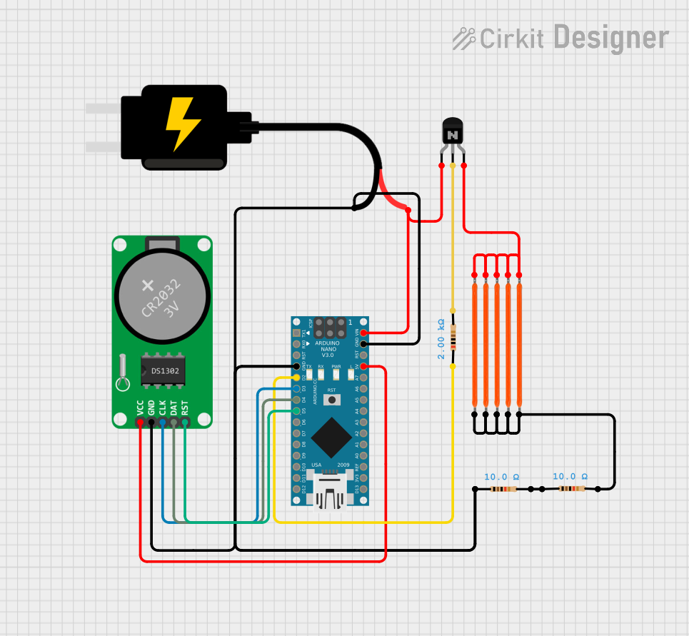
Arduino Nano-Controlled LED Lighting with RTC Scheduling

Circuit Documentation
Summary
This circuit is designed around an Arduino Nano microcontroller and includes a real-time clock (RTC-DS1302), a set of LED filaments, NPN transistors, and resistors. The Arduino Nano is programmed to control the state of an output pin based on the time provided by the RTC. The output pin drives an NPN transistor that switches a series of LEDs on or off depending on the time of day. The circuit is powered by a 5V DC source.
Component List
Arduino Nano
- Microcontroller board based on the ATmega328P
- It has a variety of digital and analog I/O pins.
LED Filament 3V
- A light-emitting diode designed to operate at 3V.
Resistor (10 Ohms)
- A passive two-terminal electrical component that implements electrical resistance as a circuit element.
Resistor (2000 Ohms)
- A passive two-terminal electrical component that implements electrical resistance as a circuit element.
NPN Transistor (CBE)
- A type of bipolar junction transistor used for amplification and switching purposes.
RTC-DS1302
- A real-time clock module that provides a timekeeping function.
DC Source 5V
- A power supply module that provides a regulated 5V output.
Wiring Details
Arduino Nano
- GND connected to the common ground net.
- D2 connected to a 2000 Ohm resistor.
- D3 connected to the CLK pin of RTC-DS1302.
- D4 connected to the DAT pin of RTC-DS1302.
- D5 connected to the RST pin of RTC-DS1302.
- VIN connected to the collector of the NPN transistor and the VCC of the DC Source 5V.
- 5V connected to the Vcc pin of RTC-DS1302.
LED Filament 3V
- GND connected to the common ground net.
- Vcc connected to the emitter of the NPN transistor.
Resistor (10 Ohms)
- One resistor connected between the common ground net and another 10 Ohm resistor.
- Another resistor connected between the common ground net and the LED filaments.
Resistor (2000 Ohms)
- Connected between the D2 pin of the Arduino Nano and the base of the NPN transistor.
NPN Transistor (CBE)
- Collector connected to the VIN of the Arduino Nano and the VCC of the DC Source 5V.
- Base connected to a 2000 Ohm resistor.
- Emitter connected to the Vcc pins of the LED filaments.
RTC-DS1302
- Vcc connected to the 5V pin of the Arduino Nano.
- GND connected to the common ground net.
- CLK connected to the D3 pin of the Arduino Nano.
- DAT connected to the D4 pin of the Arduino Nano.
- RST connected to the D5 pin of the Arduino Nano.
DC Source 5V
- VCC connected to the VIN of the Arduino Nano and the collector of the NPN transistor.
- GND connected to the common ground net.
Documented Code
#include <virtualbotixRTC.h>
virtualbotixRTC myRTC(3, 4, 5)

void setup() {
  Serial.begin(57600);
  pinMode(2, OUTPUT);
  // sec, min, hour, day of the week, day of the month, moth, year
  myRTC.setDS1302Time(00, 00, 21, 2, 22, 10, 2024);
}

void loop() {
  myRTC.updateTime();
  // Turn on the LEDs between 8 AM and 11 PM
  if(myRTC.hours >= 8 && myRTC.hours <= 23){
    digitalWrite(2, HIGH);
  }else{
    digitalWrite(2, LOW);
  }
  delay(60000); // Wait for 60 seconds before updating the time again
}
The code is written for the Arduino Nano and utilizes the virtualbotixRTC library to interface with the RTC-DS1302 module. The setup() function initializes the serial communication and sets the initial time on the RTC. The loop() function checks the current time and controls the output pin connected to the NPN transistor, which in turn controls the LED filaments based on the time of day.