
Arduino UNO Joystick-Controlled DC Motors and Linear Actuator System
View and Edit Project In Cirkit Designer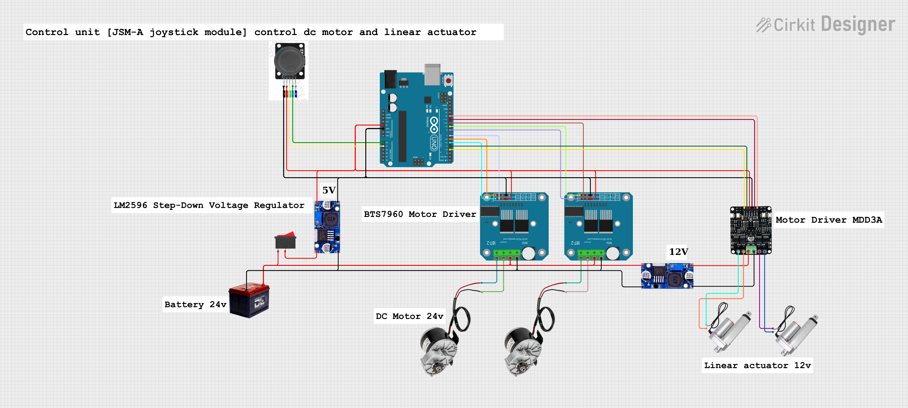
Circuit Documentation
Summary
This circuit is designed to control two DC motors and a linear actuator using an Arduino UNO and a joystick module. The joystick's X and Y axes are read to control the speed and direction of the motors and the actuator. The circuit includes various components such as motor drivers, a rocker switch, and a voltage regulator to ensure proper operation.
Component List
Arduino UNO
- Description: Microcontroller board based on the ATmega328P.
- Pins: UNUSED, IOREF, Reset, 3.3V, 5V, GND, Vin, A0, A1, A2, A3, A4, A5, SCL, SDA, AREF, D13, D12, D11, D10, D9, D8, D7, D6, D5, D4, D3, D2, D1, D0
250W 12V Electric Motor Brush Motor DC
- Description: High-power DC motor.
- Pins: POSITIF, NEGATIF
Battery 12V
- Description: Power source for the circuit.
- Pins: -, +
Linear Actuator
- Description: Device that creates motion in a straight line.
- Pins: +, -
LM2596
- Description: Voltage regulator.
- Pins: IN, OUT
Rocker Switch
- Description: Switch to control the power supply.
- Pins: 1, 2
Motor Driver
- Description: Driver for controlling motors.
- Pins: VB+, VB-, M1A, M1B, M2A, M2B, 5V, GND
BTS7960 Motor Driver
- Description: High-power motor driver.
- Pins: Pin 1, Pin 2, Pin 3, Pin 4, Pin 5, Pin 6, Pin 7, Pin 8, Pin 9, Pin 10, Pin 11, Pin 12
Joystick Module
- Description: Module to control motors and actuators using a joystick.
- Pins: SW, VRY, VRX, VCC, GND
Wiring Details
Arduino UNO
- 5V connected to VCC of Joystick Module, 5V of Motor Driver, Pin 5 of BTS7960 Motor Driver, and OUT of LM2596.
- GND connected to GND of Joystick Module, GND of Motor Driver, Pin 1 of BTS7960 Motor Driver, and OUT of LM2596.
- A0 connected to VRY of Joystick Module.
- A1 connected to VRX of Joystick Module.
- D12 connected to M2B of Motor Driver.
- D11 connected to M2A of Motor Driver.
- D10 connected to Pin 7 of BTS7960 Motor Driver.
- D9 connected to Pin 4 of BTS7960 Motor Driver.
- D8 connected to Pin 8 of BTS7960 Motor Driver.
- D7 connected to Pin 7 of BTS7960 Motor Driver.
- D6 connected to Pin 4 of BTS7960 Motor Driver.
- D5 connected to Pin 8 of BTS7960 Motor Driver.
- D4 connected to M1B of Motor Driver.
- D3 connected to M1A of Motor Driver.
250W 12V Electric Motor Brush Motor DC
- POSITIF connected to Pin 9 of BTS7960 Motor Driver.
- NEGATIF connected to Pin 10 of BTS7960 Motor Driver.
Battery 12V
- + connected to 1 of Rocker Switch, Pin 11 of BTS7960 Motor Driver, and IN of LM2596.
- - connected to Pin 12 of BTS7960 Motor Driver and IN of LM2596.
Linear Actuator
- + connected to M1A of Motor Driver.
- - connected to M1B of Motor Driver.
- + connected to M2A of Motor Driver.
- - connected to M2B of Motor Driver.
LM2596
- IN connected to 1 of Rocker Switch and Pin 11 of BTS7960 Motor Driver.
- OUT connected to 5V of Arduino UNO, 5V of Motor Driver, Pin 5 of BTS7960 Motor Driver, and OUT of LM2596.
Rocker Switch
- 1 connected to + of Battery 12V.
- 2 connected to IN of LM2596.
Motor Driver
- VB+ connected to OUT of LM2596.
- VB- connected to OUT of LM2596.
- M1A connected to + of Linear Actuator.
- M1B connected to - of Linear Actuator.
- M2A connected to + of Linear Actuator.
- M2B connected to - of Linear Actuator.
BTS7960 Motor Driver
- Pin 1 connected to GND of Arduino UNO.
- Pin 4 connected to D9 of Arduino UNO.
- Pin 5 connected to 5V of Arduino UNO.
- Pin 7 connected to D10 of Arduino UNO.
- Pin 8 connected to D8 of Arduino UNO.
- Pin 9 connected to POSITIF of 250W 12V Electric Motor Brush Motor DC.
- Pin 10 connected to NEGATIF of 250W 12V Electric Motor Brush Motor DC.
- Pin 11 connected to + of Battery 12V.
- Pin 12 connected to - of Battery 12V.
Joystick Module
- VCC connected to 5V of Arduino UNO.
- GND connected to GND of Arduino UNO.
- VRY connected to A0 of Arduino UNO.
- VRX connected to A1 of Arduino UNO.
Code Documentation
/*
 * This Arduino Sketch controls two DC motors and a linear actuator using
 * a joystick module. The joystick's X and Y axes are read to control the
 * speed and direction of the motors and the actuator.
 */

#include <Arduino.h>

// Pin definitions
const int joystickVRX = A1;
const int joystickVRY = A0;
const int motor1PWM = 9;
const int motor1DIR = 8;
const int motor2PWM = 6;
const int motor2DIR = 5;
const int actuatorPWM = 12;
const int actuatorDIR = 11;

void setup() {
  // Initialize serial communication
  Serial.begin(9600);
  // Initialize motor and actuator control pins
  pinMode(motor1PWM, OUTPUT);
  pinMode(motor1DIR, OUTPUT);
  pinMode(motor2PWM, OUTPUT);
  pinMode(motor2DIR, OUTPUT);
  pinMode(actuatorPWM, OUTPUT);
  pinMode(actuatorDIR, OUTPUT);
}

void loop() {
  // Read joystick values
  int xValue = analogRead(joystickVRX);
  int yValue = analogRead(joystickVRY);

  // Map joystick values to motor control signals
  int motor1Speed = map(xValue, 0, 1023, -255, 255);
  int motor2Speed = map(yValue, 0, 1023, -255, 255);

  // Control motor 1
  if (motor1Speed > 0) {
    digitalWrite(motor1DIR, HIGH);
    analogWrite(motor1PWM, motor1Speed);
  } else {
    digitalWrite(motor1DIR, LOW);
    analogWrite(motor1PWM, -motor1Speed);
  }

  // Control motor 2
  if (motor2Speed > 0) {
    digitalWrite(motor2DIR, HIGH);
    analogWrite(motor2PWM, motor2Speed);
  } else {
    digitalWrite(motor2DIR, LOW);
    analogWrite(motor2PWM, -motor2Speed);
  }

  // Control linear actuator
  int actuatorSpeed = map(yValue, 0, 1023, -255, 255);
  if (actuatorSpeed > 0) {
    digitalWrite(actuatorDIR, HIGH);
    analogWrite(actuatorPWM, actuatorSpeed);
  } else {
    digitalWrite(actuatorDIR, LOW);
    analogWrite(actuatorPWM, -actuatorSpeed);
  }

  // Small delay to stabilize readings
  delay(50);
}
This code initializes the necessary pins for controlling the motors and the linear actuator. It