Cirkit Designer
Your all-in-one circuit design IDE
Home /
Project Documentation
Arduino UNO Controlled LCD Display with Pushbutton Interaction
Circuit Documentation
Summary
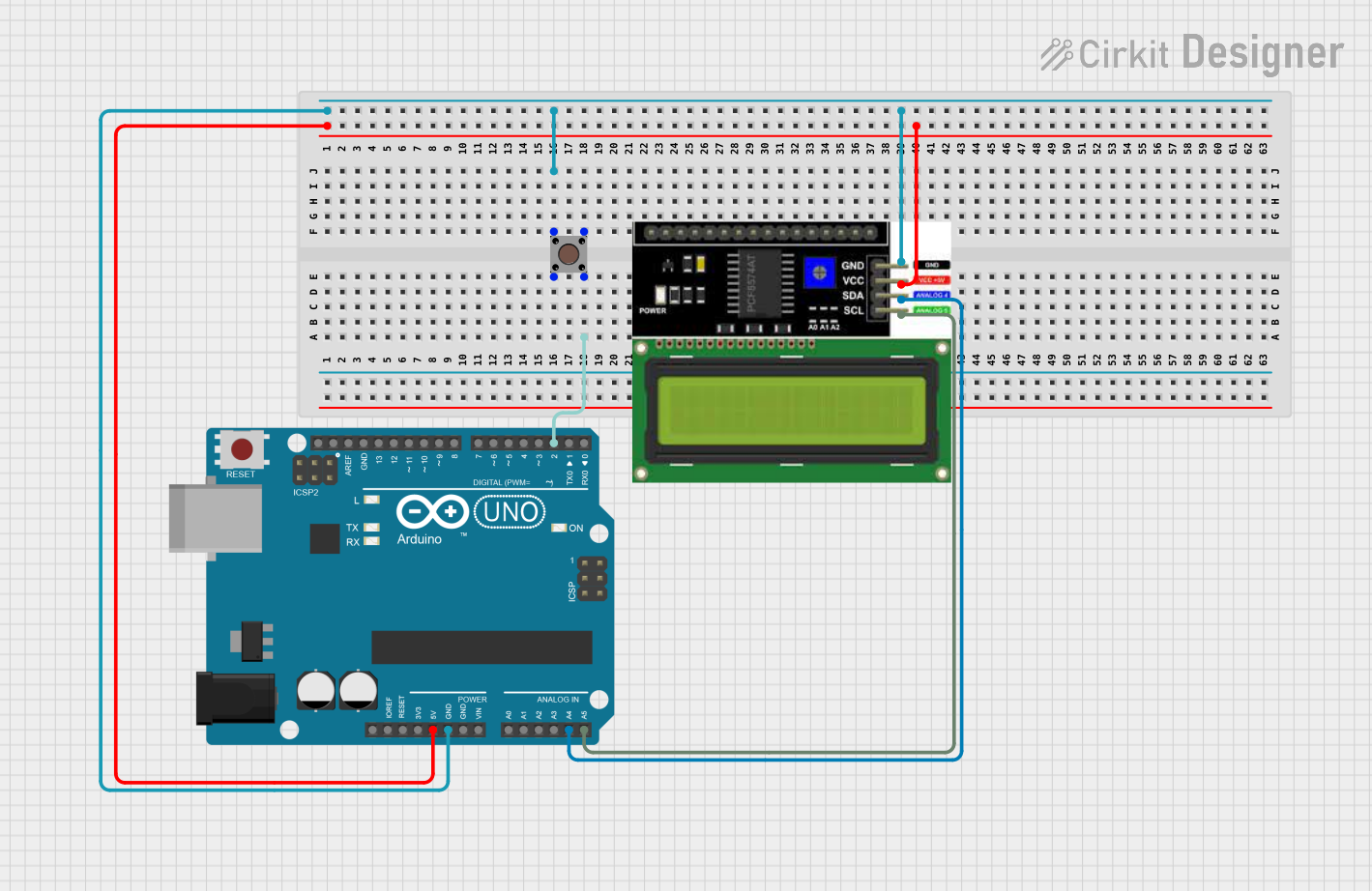
This circuit consists of an Arduino UNO microcontroller, a pushbutton, and an LCD I2C display. The Arduino UNO serves as the central processing unit, controlling the input from the pushbutton and outputting data to the LCD display. The pushbutton is used as an input device, and the LCD display is an output device that shows information to the user. The circuit is designed to read the state of the pushbutton and display relevant information on the LCD screen.
Component List
Arduino UNO
- Description: A microcontroller board based on the ATmega328P.
- Pins: UNUSED, IOREF, Reset, 3.3V, 5V, GND, Vin, A0-A5, SCL, SDA, AREF, D0-D13.
Pushbutton
- Description: A simple switch mechanism for controlling some aspect of a machine or a process.
- Pins: Pin 3 (out), Pin 4 (out), Pin 1 (in), Pin 2 (in).
LCD I2C Display
- Description: A liquid crystal display that uses the I2C protocol for communication.
- Pins: GND, VCC, SDA, SCL.
Wiring Details
Arduino UNO
- GND: Connected to Pushbutton (Pin 4) and LCD I2C Display (GND).
- 5V: Provides power to the LCD I2C Display (VCC).
- D2: Connected to Pushbutton (Pin 1).
- A4 (SDA): Connected to LCD I2C Display (SDA).
- A5 (SCL): Connected to LCD I2C Display (SCL).
Pushbutton
- Pin 1 (in): Connected to Arduino UNO (D2).
- Pin 4 (out): Connected to Arduino UNO (GND).
LCD I2C Display
- GND: Connected to Arduino UNO (GND).
- VCC: Powered by Arduino UNO (5V).
- SDA: Connected to Arduino UNO (A4).
- SCL: Connected to Arduino UNO (A5).
Documented Code
Arduino UNO Code (sketch.ino)
void setup() {
  // put your setup code here, to run once:

}

void loop() {
  // put your main code here, to run repeatedly:

}
Additional Notes
- The provided code is a template and does not contain any functional code for interacting with the pushbutton or the LCD I2C display. The setup and loop functions need to be populated with the appropriate code to initialize the display and read the pushbutton state.
- The
documentation.txtfile is empty and does not provide additional information about the code.