
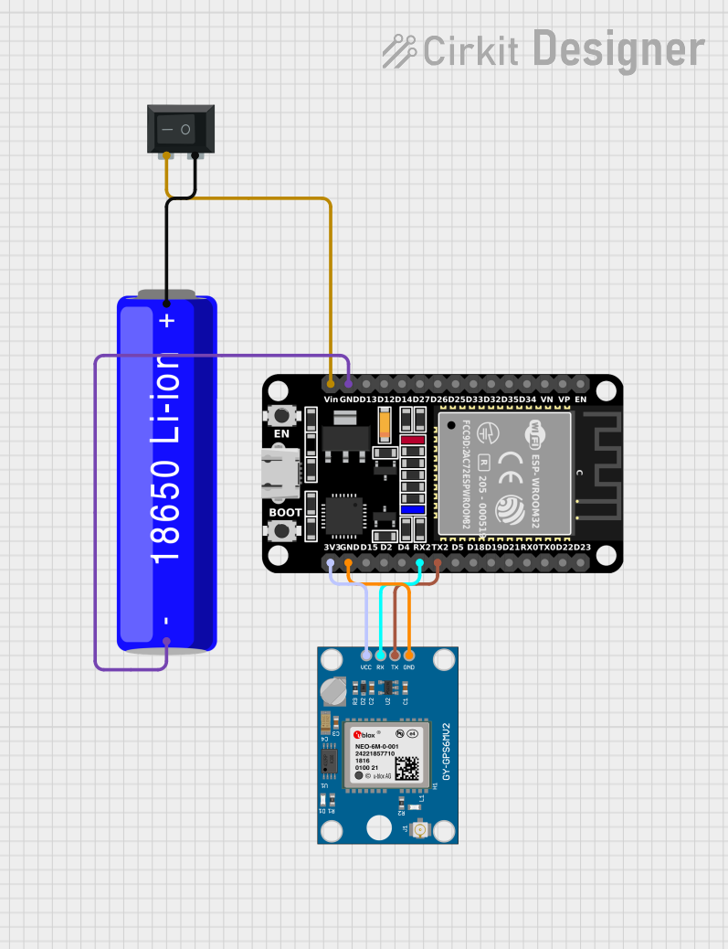
Circuit Documentation
Summary
This document provides a detailed overview of a circuit that integrates an ESP32 microcontroller, a Neo 6M GPS module, a 18650 Li-ion battery, and a Rocker Switch (SPST). The ESP32 is programmed to read GPS data from the Neo 6M module and output the information via serial communication. The circuit is powered by a 18650 Li-ion battery, with a rocker switch to control the power supply.
Component List
ESP32 (30 pin)
- Description: A powerful microcontroller with built-in Wi-Fi and Bluetooth capabilities.
- Pins: EN, VP, VN, D34, D35, D32, D33, D25, D26, D27, D14, D12, D13, GND, Vin, D23, D22, TX0, RX0, D21, D19, D18, D5, TX2, RX2, D4, D2, D15, 3V3
Neo 6M GPS Module
- Description: A GPS module capable of providing location, speed, and time data.
- Pins: GND, TX, RX, VCC
18650 Li-ion Battery
- Description: A rechargeable lithium-ion battery commonly used in portable electronics.
- Pins: -, +
Rocker Switch (SPST)
- Description: A single-pole single-throw switch used to control the power supply.
- Pins: 1, 2
Wiring Details
ESP32 (30 pin)
- GND is connected to the GND of the Neo 6M GPS Module and the - of the 18650 Li-ion Battery.
- Vin is connected to pin 2 of the Rocker Switch.
- TX2 is connected to the TX of the Neo 6M GPS Module.
- RX2 is connected to the RX of the Neo 6M GPS Module.
- 3V3 is connected to the VCC of the Neo 6M GPS Module.
Neo 6M GPS Module
- GND is connected to the GND of the ESP32.
- TX is connected to TX2 of the ESP32.
- RX is connected to RX2 of the ESP32.
- VCC is connected to 3V3 of the ESP32.
18650 Li-ion Battery
- - is connected to the GND of the ESP32.
- + is connected to pin 1 of the Rocker Switch.
Rocker Switch (SPST)
- Pin 1 is connected to the + of the 18650 Li-ion Battery.
- Pin 2 is connected to the Vin of the ESP32.
Code Documentation
sketch.ino
#include <TinyGPS++.h>
#include <TinyGPSPlus.h>

#define GPS_BAUDRATE 9600  // The default baudrate of NEO-6M is 9600

TinyGPSPlus gps;  // the TinyGPS++ object

void setup() {
  Serial.begin(9600);
  Serial2.begin(GPS_BAUDRATE); // serial2 for GPS UART

  Serial.println(F("ESP32 - GPS module_Simulation"));
}

void loop() {
  if (Serial2.available() > 0) {
    if (gps.encode(Serial2.read())) {
      if (gps.location.isValid()) {
        Serial.print(F("Latitude: "));
        Serial.println(gps.location.lat(), 6);

        Serial.print(F("Longitude: "));
        Serial.println(gps.location.lng(), 6);

        Serial.print(F("Altitude: "));
        if (gps.altitude.isValid())
          Serial.println(gps.altitude.meters());
        else
          Serial.println(F("INVALID"));
      } else {
        Serial.println(F("Location: INVALID"));
      }

      Serial.print(F("Speed: "));
      if (gps.speed.isValid()) {
        Serial.print(gps.speed.kmph());
        Serial.println(F(" km/h"));
      } else {
        Serial.println(F("INVALID"));
      }

      Serial.print(F("GPS date&time: "));
      if (gps.date.isValid() && gps.time.isValid()) {
        Serial.print(gps.date.year());
        Serial.print(F("-"));
        Serial.print(gps.date.month());
        Serial.print(F("-"));
        Serial.print(gps.date.day());
        Serial.print(F(" "));
        Serial.print(gps.time.hour());
        Serial.print(F(":"));
        Serial.print(gps.time.minute());
        Serial.print(F(":"));
        Serial.println(gps.time.second());
      } else {
        Serial.println(F("INVALID"));
      }

      Serial.println();
    }
  }

  if (millis() > 5000 && gps.charsProcessed() < 10)
    Serial.println(F("No GPS data received: check wiring"));
}
This code initializes the ESP32 to communicate with the Neo 6M GPS module via UART (Serial2). It reads GPS data and prints the latitude, longitude, altitude, speed, and date & time to the serial monitor. If no GPS data is received within 5 seconds, it prompts to check the wiring.