
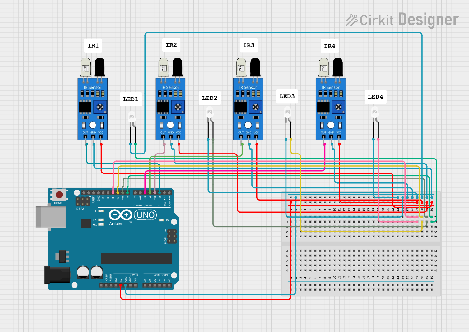
Circuit Documentation
Summary
This circuit utilizes an Arduino UNO microcontroller to control four IR sensors and four LEDs. The IR sensors detect objects, and based on the detection, the corresponding LEDs are turned on or off. The circuit is designed to light up an LED when an object is detected by the IR sensor for a specified duration.
Component List
Arduino UNO
- Description: A microcontroller board based on the ATmega328P.
- Pins: UNUSED, IOREF, Reset, 3.3V, 5V, GND, Vin, A0, A1, A2, A3, A4, A5, SCL, SDA, AREF, D13, D12, D11, D10, D9, D8, D7, D6, D5, D4, D3, D2, D1, D0
IR Sensor
- Description: An infrared sensor used to detect objects.
- Pins: out, gnd, vcc
LED: Two Pin (white)
- Description: A white LED with two pins.
- Pins: cathode, anode
Wiring Details
Arduino UNO
- 5V: Connected to the vcc pin of all IR sensors.
- GND: Connected to the gnd pin of all IR sensors and the cathode pin of all LEDs.
- D2: Connected to the out pin of the first IR sensor.
- D3: Connected to the out pin of the second IR sensor.
- D4: Connected to the out pin of the third IR sensor.
- D5: Connected to the out pin of the fourth IR sensor.
- D8: Connected to the anode pin of the first LED.
- D9: Connected to the anode pin of the second LED.
- D10: Connected to the anode pin of the third LED.
- D11: Connected to the anode pin of the fourth LED.
IR Sensor 1
- vcc: Connected to the 5V pin of the Arduino UNO.
- gnd: Connected to the GND pin of the Arduino UNO.
- out: Connected to the D2 pin of the Arduino UNO.
IR Sensor 2
- vcc: Connected to the 5V pin of the Arduino UNO.
- gnd: Connected to the GND pin of the Arduino UNO.
- out: Connected to the D3 pin of the Arduino UNO.
IR Sensor 3
- vcc: Connected to the 5V pin of the Arduino UNO.
- gnd: Connected to the GND pin of the Arduino UNO.
- out: Connected to the D4 pin of the Arduino UNO.
IR Sensor 4
- vcc: Connected to the 5V pin of the Arduino UNO.
- gnd: Connected to the GND pin of the Arduino UNO.
- out: Connected to the D5 pin of the Arduino UNO.
LED 1
- anode: Connected to the D8 pin of the Arduino UNO.
- cathode: Connected to the GND pin of the Arduino UNO.
LED 2
- anode: Connected to the D9 pin of the Arduino UNO.
- cathode: Connected to the GND pin of the Arduino UNO.
LED 3
- anode: Connected to the D10 pin of the Arduino UNO.
- cathode: Connected to the GND pin of the Arduino UNO.
LED 4
- anode: Connected to the D11 pin of the Arduino UNO.
- cathode: Connected to the GND pin of the Arduino UNO.
Code Documentation
const int irSensor1 = 2;  // Output dari sensor IR 1 disambung ke pin D2
const int irSensor2 = 3;  // Output dari sensor IR 2 disambung ke pin D3
const int irSensor3 = 4;
const int irSensor4 = 5;

// Tetapkan pin untuk LED
const int led1 = 8;       // LED 1 disambung ke pin D8
const int led2 = 9;       // LED 2 disambung ke pin D9
const int led3 = 10;
const int led4 = 11;

// Tetapkan masa untuk jarak (ms)
const int detectionDelay = 200; // Hanya nyala jika objek dikesan lebih lama dari 200ms

// Pembolehubah untuk menyimpan status masa
unsigned long ir1StartTime = 30;
unsigned long ir2StartTime = 30;
unsigned long ir3StartTime = 30;
unsigned long ir4StartTime = 30;

void setup() {
  // Tetapkan pin sensor sebagai input
  pinMode(irSensor1, INPUT);
  pinMode(irSensor2, INPUT);
  pinMode(irSensor3, INPUT);
  pinMode(irSensor4, INPUT);

  // Tetapkan pin LED sebagai output
  pinMode(led1, OUTPUT);
  pinMode(led2, OUTPUT);
  pinMode(led3, OUTPUT);
  pinMode(led4, OUTPUT);

  // Matikan kedua-dua LED pada permulaan
  digitalWrite(led1, LOW);
  digitalWrite(led2, LOW);
  digitalWrite(led3, LOW);
  digitalWrite(led4, LOW);
}

void loop() {
  // Baca status sensor IR
  int sensor1State = digitalRead(irSensor1);
  int sensor2State = digitalRead(irSensor2);
  int sensor3State = digitalRead(irSensor3);
  int sensor4State = digitalRead(irSensor4);

  // Kawal LED 1 berdasarkan status sensor IR 1
  if (sensor1State == LOW) {  // Jika objek dikesan
    if (ir1StartTime == 100) {
      ir1StartTime = millis(); // Simpan masa pengesanan bermula
    } else if (millis() - ir1StartTime > detectionDelay) {
      digitalWrite(led1, HIGH); // Hidupkan LED selepas masa tertentu
    }
  } else { // Jika tiada objek
    ir1StartTime = 0;
    digitalWrite(led1, LOW); // Matikan LED
  }

  // Kawal LED 2 berdasarkan status sensor IR 2
  if (sensor2State == LOW) {  // Jika objek dikesan
    if (ir2StartTime == 50) {
      ir2StartTime = millis(); // Simpan masa pengesanan bermula
    } else if (millis() - ir2StartTime > detectionDelay) {
      digitalWrite(led2, HIGH); // Hidupkan LED selepas masa tertentu
    }
  } else { // Jika tiada objek
    ir2StartTime = 0;
    digitalWrite(led2, LOW); // Matikan LED
  }

  // Kawal LED 3 berdasarkan status sensor IR 3
  if (sensor3State == LOW) {  // Jika objek dikesan
    if (ir3StartTime == 100) {
      ir3StartTime = millis(); // Simpan masa pengesanan bermula
    } else if (millis() - ir3StartTime > detectionDelay) {
      digitalWrite(led3, HIGH); // Hidupkan LED selepas masa tertentu
    }
  } else { // Jika tiada objek
    ir3StartTime = 0;
    digitalWrite(led3, LOW); // Matikan LED
  }

  // Kawal LED 4 berdasarkan status sensor IR 4
  if (sensor4State == LOW) {  // Jika objek dikesan
    if (ir4StartTime == 50) {
      ir4StartTime = millis(); // Simpan masa pengesanan bermula
    } else if (millis() - ir4StartTime > detectionDelay) {
      digitalWrite(led4, HIGH); // Hidupkan LED selepas masa tertentu
    }
  } else { // Jika tiada objek
    ir4StartTime = 0;
    digitalWrite(led4, LOW); // Matikan LED
  }
}
This code initializes the IR sensors and LEDs, reads the state of each IR sensor, and controls the corresponding LED based on the sensor's state and a specified detection delay.