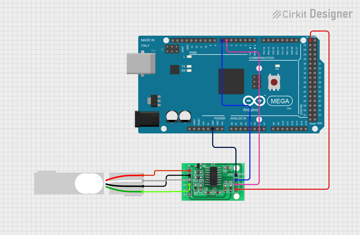
Arduino Mega 2560 Based Load Cell Weight Measurement System

Circuit Documentation
Summary
This circuit integrates an Arduino Mega 2560 microcontroller with an HX711 Bridge Sensor Interface and a Load Cell. The HX711 is used to amplify and convert the Load Cell's differential signal output to a single-ended digital signal that the Arduino can process. The Load Cell acts as a weighing sensor, and the HX711 serves as an analog-to-digital converter specifically designed for this type of sensor. The Arduino Mega 2560 is programmed to read the digital output from the HX711 and perform further processing or actions based on the measured weight.
Component List
Arduino Mega 2560
- Description: A microcontroller board based on the ATmega2560, with numerous digital and analog I/O pins, communication interfaces, and a USB connection for programming and serial communication.
- Purpose: Acts as the central processing unit of the circuit, reading sensor data, executing the embedded code, and potentially controlling other devices or reporting data.
Load Cell - Red/white/black/green
- Description: A transducer that converts force into an electrical signal. This Load Cell has four wires corresponding to the Excitation (E+/E-) and Signal (A+/A-) outputs.
- Purpose: Measures the weight or force applied to it and generates an electrical signal proportional to the force.
HX711 - Bridge Sensor Interface
- Description: A precision 24-bit analog-to-digital converter (ADC) designed for weigh scales and industrial control applications to interface directly with a bridge sensor.
- Purpose: Amplifies the small signal from the Load Cell and converts it to a digital value for the Arduino to read.
Wiring Details
Arduino Mega 2560
- 5V connected to HX711 3.3/3.5V Supply
- GND connected to HX711 GND - GROUND
- D6 PWM connected to HX711 SCK - CLOCK (IN)
- D7 PWM connected to HX711 DATA (OUT)
Load Cell - Red/white/black/green
- E+ connected to HX711 E+
- A- connected to HX711 A-
- E- connected to HX711 E-
- A+ connected to HX711 A+
HX711 - Bridge Sensor Interface
- E+ connected to Load Cell E+
- A- connected to Load Cell A-
- E- connected to Load Cell E-
- A+ connected to Load Cell A+
- GND - GROUND connected to Arduino Mega 2560 GND
- SCK - CLOCK (IN) connected to Arduino Mega 2560 D6 PWM
- DATA (OUT) connected to Arduino Mega 2560 D7 PWM
- 3.3/3.5V Supply connected to Arduino Mega 2560 5V
Documented Code
Arduino Mega 2560 - sketch.ino
void setup() {
  // put your setup code here, to run once:

}

void loop() {
  // put your main code here, to run repeatedly:

}
Arduino Mega 2560 - documentation.txt
(No additional documentation provided for the code)
This concludes the documentation for the given circuit. The code provided is a template and does not include specific functionality. It should be expanded to initialize the HX711, read data from it, and perform any required processing or output based on the Load Cell's readings.