
ESP32 and A988 Driver Controlled NEMA 17 Stepper Motor System
View and Edit Project In Cirkit Designer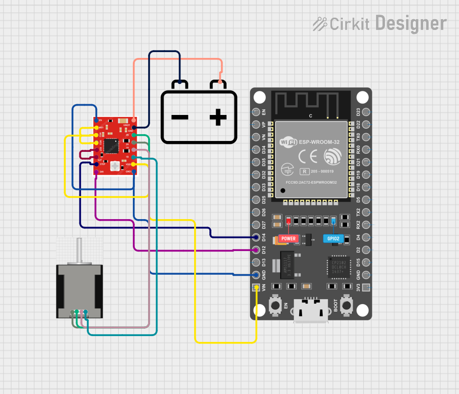
Circuit Documentation
Summary
This circuit is designed to control a NEMA 17 stepper motor using an ESP32 microcontroller and an A988 driver. The ESP32 sends control signals to the A988 driver, which in turn drives the stepper motor. A 12V battery is used to power the A988 driver and the stepper motor.
Component List
ESP 32 DEVKIT V1 (30 pins)
- Description: A development board based on the ESP32 microcontroller.
- Pins: EN, VP, VN, D34, D35, D32, D33, D25, D26, D27, D14, D12, D13, GND, VIN, 3V3, D15, D2, D4, RX2, TX2, D5, D18, D19, D21, RX0, TX0, D22, D23
NEMA 17 HS4401
- Description: A bipolar stepper motor.
- Pins: RED (B2), BLACK (B1), BLUE (A2), GREEN (A1)
A988 DRIVER
- Description: A stepper motor driver.
- Pins: VMOT, GND, 2B, 2A, 1A, 1B, VDD, EN, MS1, MS2, MS3, RST, SLP, STEP, DIR
12V Battery
- Description: A 12V power source.
- Pins: +, -
Wiring Details
ESP 32 DEVKIT V1 (30 pins)
- D14 is connected to STEP on the A988 DRIVER.
- D12 is connected to DIR on the A988 DRIVER.
- GND is connected to GND and EN on the A988 DRIVER.
- VIN is connected to MS2, MS3, VDD, and MS1 on the A988 DRIVER.
NEMA 17 HS4401
- RED (B2) is connected to 2A on the A988 DRIVER.
- BLACK (B1) is connected to 2B on the A988 DRIVER.
- BLUE (A2) is connected to 1A on the A988 DRIVER.
- GREEN (A1) is connected to 1B on the A988 DRIVER.
A988 DRIVER
- VMOT is connected to + on the 12V Battery.
- GND is connected to - on the 12V Battery.
- RST is connected to SLP on the A988 DRIVER.
12V Battery
- + is connected to VMOT on the A988 DRIVER.
- - is connected to GND on the A988 DRIVER.
Code Documentation
ESP 32 DEVKIT V1 (30 pins)
/*
 * This Arduino Sketch is designed to control a NEMA 17 stepper motor using
 * an ESP32 microcontroller and an A988 driver. The code initializes the
 * necessary pins and runs the stepper motor in an anticlockwise direction.
 */

#define STEP_PIN 14
#define DIR_PIN 12

void setup() {
  // Set the pins as output
  pinMode(STEP_PIN, OUTPUT);
  pinMode(DIR_PIN, OUTPUT);

  // Set the direction to anticlockwise
  digitalWrite(DIR_PIN, LOW);
}

void loop() {
  // Rotate the stepper motor
  digitalWrite(STEP_PIN, HIGH);
  delayMicroseconds(1000);
  digitalWrite(STEP_PIN, LOW);
  delayMicroseconds(1000);
}
A988 DRIVER
/*
 * This Arduino Sketch is designed to control a NEMA 17 stepper motor using
 * an ESP32 microcontroller and an A988 driver. The code initializes the
 * necessary pins and runs the stepper motor in an anticlockwise direction.
 */

#define STEP_PIN 14
#define DIR_PIN 12

void setup() {
  // Set the pins as output
  pinMode(STEP_PIN, OUTPUT);
  pinMode(DIR_PIN, OUTPUT);

  // Set the direction to anticlockwise
  digitalWrite(DIR_PIN, LOW);
}

void loop() {
  // Rotate the stepper motor
  digitalWrite(STEP_PIN, HIGH);
  delayMicroseconds(1000);
  digitalWrite(STEP_PIN, LOW);
  delayMicroseconds(1000);
}
This documentation provides a comprehensive overview of the circuit, including a summary, detailed component list, wiring details, and the code used to control the stepper motor.