
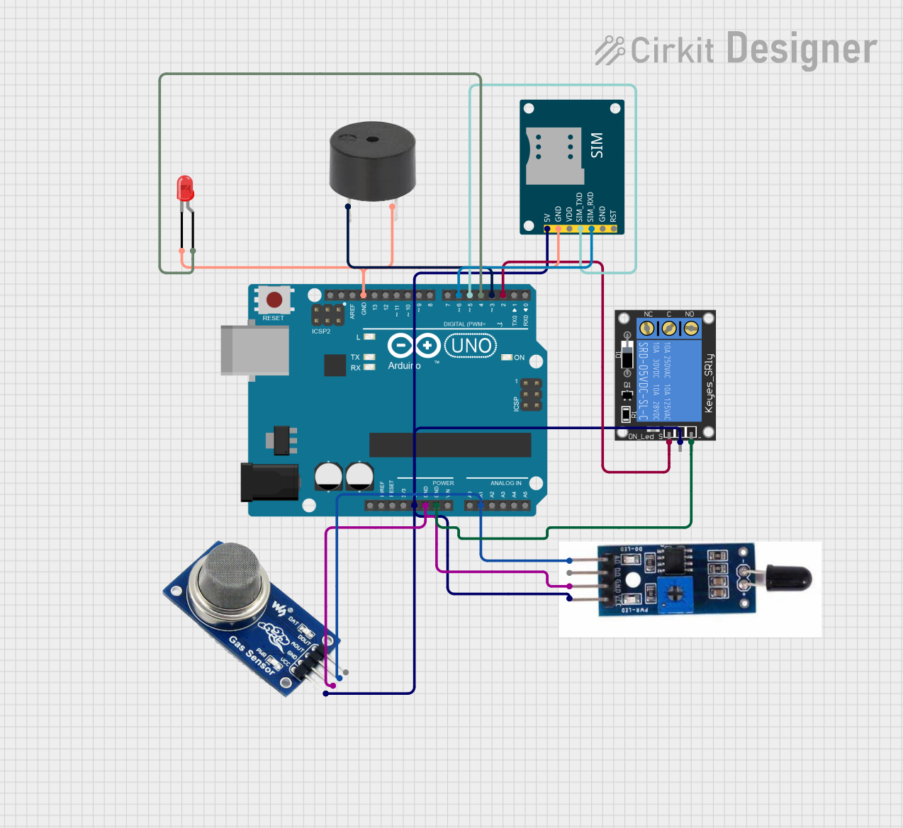
Circuit Documentation
Summary
The circuit in question is designed to monitor environmental conditions using a gas sensor (MQ2) and a heat flame sensor. It utilizes an Arduino UNO as the central microcontroller to process sensor data and control peripheral devices such as a buzzer, an LED, and a relay. Additionally, the circuit includes a SIM800L GSM Module for sending alerts via SMS when certain conditions are met. The circuit is powered by a 5V supply, which is distributed to the various components.
Component List
Arduino UNO
- Microcontroller board based on the ATmega328P
- It has 14 digital input/output pins, 6 analog inputs, a 16 MHz quartz crystal, a USB connection, a power jack, an ICSP header, and a reset button.
MQ2 Gas Sensor
- A gas sensor used for detecting a variety of gases including LPG, smoke, and alcohol.
- It has four pins: VCC, GND, AOUT (analog output), and DOUT (digital output).
Buzzer
- An electromechanical component that produces sound.
- It has two pins: PIN (signal input) and GND.
SIM800L GSM Module
- A compact GSM/GPRS module for mobile communication.
- It has six pins: 5V, GND, VDD, SIM_TXD (transmit data), SIM_RXD (receive data), and RST (reset).
Heat Flame Sensor
- A sensor for detecting flames and other sources of heat.
- It has four pins: AO (analog output), DO (digital output), GND, and VCC.
1-Channel Relay (5V 10A)
- An electrically operated switch that can be controlled by an Arduino.
- It has six pins: NC (normally closed), signal (control input), C (common), power (VCC), NO (normally open), and ground.
LED: Two Pin (red)
- A basic red light-emitting diode.
- It has two pins: cathode (-) and anode (+).
Wiring Details
Arduino UNO
- 5V: Connected to the 5V power rail supplying power to the MQ2, SIM800L GSM Module, 1-Channel Relay, and Heat Flame Sensor.
- GND: Connected to the ground rail, which is common for MQ2, Heat Flame Sensor, SIM800L GSM Module, buzzer, and LED.
- A1: Connected to the analog outputs of both MQ2 and Heat Flame Sensor.
- D2: Connected to the signal pin of the 1-Channel Relay.
- D3: Connected to the PIN of the buzzer.
- D4: Connected to the anode of the LED.
- D5: Connected to the SIM_TXD of the SIM800L GSM Module.
- D6: Connected to the SIM_RXD of the SIM800L GSM Module.
MQ2 Gas Sensor
- VCC: Connected to the 5V power rail.
- GND: Connected to the ground rail.
- AOUT: Connected to the A1 pin on the Arduino UNO.
Buzzer
- PIN: Connected to the D3 pin on the Arduino UNO.
- GND: Connected to the ground rail.
SIM800L GSM Module
- 5V: Connected to the 5V power rail.
- GND: Connected to the ground rail.
- SIM_TXD: Connected to the D5 pin on the Arduino UNO.
- SIM_RXD: Connected to the D6 pin on the Arduino UNO.
Heat Flame Sensor
- VCC: Connected to the 5V power rail.
- GND: Connected to the ground rail.
- AO: Connected to the A1 pin on the Arduino UNO.
1-Channel Relay (5V 10A)
- Power: Connected to the 5V power rail.
- Ground: Connected to the ground rail.
- Signal: Connected to the D2 pin on the Arduino UNO.
LED: Two Pin (red)
- Anode: Connected to the D4 pin on the Arduino UNO.
- Cathode: Connected to the ground rail.
Documented Code
#include <SoftwareSerial.h>

// Pin definitions
const int flameSensorPin = A1; // Both MQ2 and Flame Sensor connected to A1
const int relayPin = 2;
const int buzzerPin = 3;
const int ledPin = 4;
const int simTxPin = 5;
const int simRxPin = 6;

// Create a SoftwareSerial object for the GSM module
SoftwareSerial sim800l(simTxPin, simRxPin);

void setup() {
  // Initialize serial communication for debugging
  Serial.begin(9600);

  // Initialize the SoftwareSerial port for the GSM module
  sim800l.begin(9600);

  // Initialize pins
  pinMode(flameSensorPin, INPUT);
  pinMode(relayPin, OUTPUT);
  pinMode(buzzerPin, OUTPUT);
  pinMode(ledPin, OUTPUT);
}

void loop() {
  // Read sensor values
  int sensorValue = analogRead(flameSensorPin);
  Serial.print("Sensor Value: ");
  Serial.println(sensorValue);

  // Example condition to activate relay, buzzer, and LED
  if (sensorValue > 500) { // Threshold value for demonstration
    digitalWrite(relayPin, HIGH);
    digitalWrite(buzzerPin, HIGH);
    digitalWrite(ledPin, HIGH);

    // Send alert via GSM module
    sendAlert("Sensor value exceeded threshold!");
  } else {
    digitalWrite(relayPin, LOW);
    digitalWrite(buzzerPin, LOW);
    digitalWrite(ledPin, LOW);
  }

  delay(1000); // Delay for 1 second
}

void sendAlert(String message) {
  sim800l.println("AT+CMGF=1"); // Set SMS mode to text
  delay(100);
  sim800l.println("AT+CMGS=\"+1234567890\""); // Replace with the recipient's phone number
  delay(100);
  sim800l.println(message); // The SMS message
  delay(100);
  sim800l.write(26); // ASCII code for CTRL+Z to send the SMS
  delay(1000);
}
This code is designed to read sensor data from the flame sensor and MQ2 gas sensor, and if a certain threshold is exceeded, it activates a relay, buzzer, and LED. Additionally, it sends an alert via the SIM800L GSM Module. The code includes setup and loop functions, as well as a custom sendAlert function for sending SMS messages.