Adafruit Crickit Controlled Robotics Platform with Micro:bit
Circuit Documentation
Summary
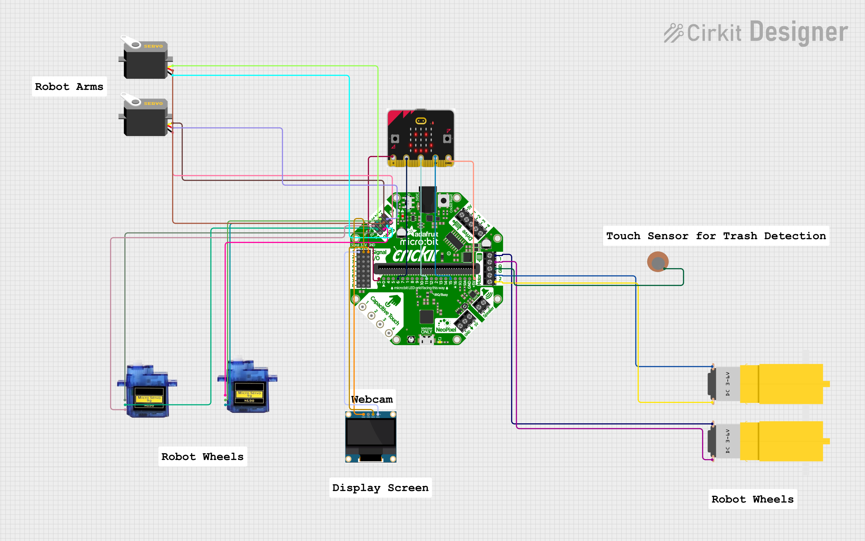
The circuit in question is designed to control various motors and servos, likely for a robotics or automation project. It includes two hobby motors, two micro servos, two standard servos, a piezo sensor, an OLED display, and a microcontroller board (micro:bit) interfaced with an Adafruit Crickit board which acts as an expansion module providing power and signal control to the connected actuators and sensors.
Component List
Motors
- Motor amarillo motorreductor hobby: A yellow hobby geared motor that requires a power supply (Vcc) and a ground connection (GND).
Servos
- Micro servo 9G: A small and lightweight servo motor with three connections: ground (GND), power (+5V), and control signal (PWM).
- Servo: A generic servo motor with three connections: ground (gnd), power (vcc), and control signal (pulse).
Control Boards
- Adafruit Crickit for micro:bit: An expansion board for the micro:bit that provides multiple input/output options including analog inputs, motor outputs, servo control, and capacitive touch inputs.
- micro:bit: A small microcontroller board with a selection of pins for I/O, power (3.3V), and ground (GND).
Sensors and Displays
- Piezo Sensor: A simple electronic device that can be used to detect vibrations, impacts, or touch. It has two connections: positive (+) and negative (-).
- 0.96" OLED: A small display module with four connections: ground (GND), power (VDD), clock (SCK), and data (SDA).
Comments
- Comment: Placeholder components that may represent annotations or notes in the circuit design.
Wiring Details
Motor amarillo motorreductor hobby
- Vcc connected to Adafruit Crickit's MOTOR_XA_OUT
- GND connected to Adafruit Crickit's MOTOR_XB_OUT
Micro servo 9G
- GND connected to Adafruit Crickit's GND
- +5V connected to Adafruit Crickit's 5.0V
- PWM connected to Adafruit Crickit's SERVOX
Servo
- gnd connected to Adafruit Crickit's GND
- vcc connected to Adafruit Crickit's 5.0V
- pulse connected to Adafruit Crickit's SERVOX
Adafruit Crickit for micro:bit
- Various connections to motors, servos, sensors, and micro:bit as detailed in the individual components.
micro:bit
- 3.3V connected to Adafruit Crickit's #15
- pin 0, pin 1, pin 2 connected to Adafruit Crickit's #3, #6, #11 respectively
- GND connected to Adafruit Crickit's +3V
Piezo Sensor
- (-) connected to Adafruit Crickit's GND
0.96" OLED
- SDA connected to Adafruit Crickit's ANALOG1
- SCK connected to Adafruit Crickit's 3.3V
- GND connected to Adafruit Crickit's GND
Documented Code
No code has been provided for the microcontrollers in the circuit. Typically, the code would be used to control the behavior of the motors and servos, read sensor data, and display information on the OLED screen. The code would be written in a suitable programming language for the micro:bit, such as Python or JavaScript, and would include initialization of I/O pins, control loops, and possibly communication protocols for the OLED display.