
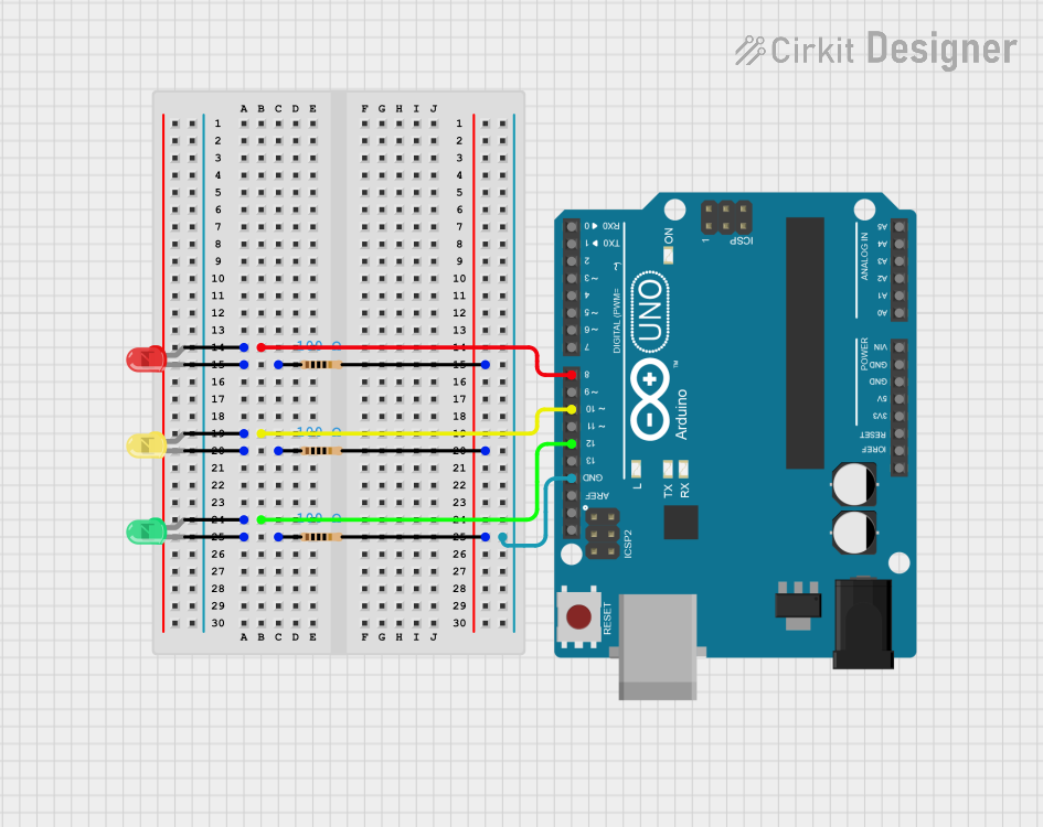
Circuit Documentation
Summary
The circuit consists of an Arduino UNO microcontroller used to control three LEDs (red, yellow, and green) through digital pins D8, D10, and D12, respectively. Each LED is connected in series with a 100 Ohm resistor to limit the current. The cathodes of the LEDs are connected to the ground (GND) through the resistors, and the anodes are connected to their respective control pins on the Arduino. The microcontroller runs a program that sequentially turns on the red LED for 3 seconds, the yellow LED for 1 second, and then blinks the green LED with a specific pattern.
Component List
Resistor
- Description: A passive two-terminal electrical component that implements electrical resistance as a circuit element.
- Purpose: To limit the current flowing through the LEDs, preventing damage.
- Properties: 100 Ohms resistance
LED: Two Pin (red)
- Description: A two-pin light-emitting diode that emits red light when powered.
- Purpose: To provide a visual indication when powered by the Arduino.
LED: Two Pin (green)
- Description: A two-pin light-emitting diode that emits green light when powered.
- Purpose: To provide a visual indication when powered by the Arduino.
LED: Two Pin (yellow)
- Description: A two-pin light-emitting diode that emits yellow light when powered.
- Purpose: To provide a visual indication when powered by the Arduino.
Arduino UNO
- Description: A microcontroller board based on the ATmega328P.
- Purpose: To control the LEDs by providing power to them through its digital pins.
Wiring Details
Resistor (100 Ohms)
- Pin1: Connected to the cathode of the corresponding LED.
- Pin2: Connected to the common node shared with other resistors, leading to the GND pin on the Arduino UNO.
LED: Two Pin (red)
- Cathode: Connected to Pin1 of the corresponding resistor.
- Anode: Connected to digital pin D8 on the Arduino UNO.
LED: Two Pin (green)
- Cathode: Connected to Pin1 of the corresponding resistor.
- Anode: Connected to digital pin D12 on the Arduino UNO.
LED: Two Pin (yellow)
- Cathode: Connected to Pin1 of the corresponding resistor.
- Anode: Connected to digital pin D10 on the Arduino UNO.
Arduino UNO
- D8: Connected to the anode of the red LED.
- D10: Connected to the anode of the yellow LED.
- D12: Connected to the anode of the green LED.
- GND: Connected to the common node shared by the resistors.
Documented Code
void setup()
{
  // Initialize digital pins as outputs
  pinMode(8, OUTPUT); // Red LED
  pinMode(10, OUTPUT); // Yellow LED
  pinMode(12, OUTPUT); // Green LED
}

void loop()
{
  // Red LED sequence
  digitalWrite(8, HIGH); // Turn on red LED for 3 seconds
  delay(3000);
  digitalWrite(8, LOW); // Turn off red LED

  // Yellow LED sequence
  digitalWrite(10, HIGH); // Turn on yellow LED for 1 second
  delay(1000);
  digitalWrite(10, LOW); // Turn off yellow LED

  // Green LED sequence
  digitalWrite(12, HIGH); // Turn on green LED for 3 seconds
  delay(3000);
  digitalWrite(12, LOW); // Turn off green LED
  delay(500);

  // Green LED blinking pattern
  for (int i = 0; i < 3; i++) {
    digitalWrite(12, HIGH); // Blink green LED on
    delay(500);
    digitalWrite(12, LOW); // Blink green LED off
    delay(500);
  }

  delay(1000); // Wait for 1 second before restarting the loop
}
This code is designed to run on the Arduino UNO and controls the sequence of LED illumination. The red LED is turned on for 3 seconds, followed by the yellow LED for 1 second. The green LED is then turned on for 3 seconds and blinks three times with a 500ms on-off cycle. The loop then restarts after a 1-second pause.